3-6. Adjustments
3-51 CLP-621 & CLP-631
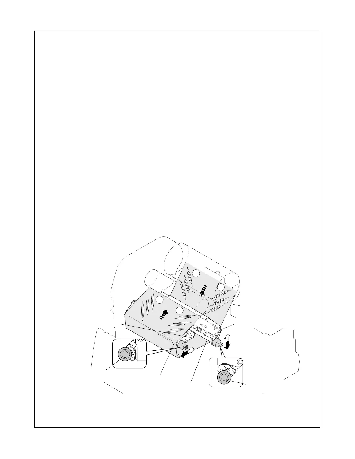
• If wrinkles are found on the right side (“a’ ” in the figure), turn the knob
counterclockwise.
• If wrinkles are found at around center, find the side (either front or rear) and turn the
knob accordingly.
3. Visually check on the supply side for ribbon wrinkles.
Since ribbon is pulled stronger on the shorter ribbon path side, wrinkles appear on the
longer path side.
During printing the self print patterns, check wrinkles and correct ribbon travel as
follow:
• If wrinkles are found on the left side (“b” in the figure), turn the Ribbon Left-Right
Balance Adjustment Knob (Rear) counterclockwise.
• If wrinkles are found on the right side (“b’ ” in the figure), turn the knob clockwise.
• If wrinkles are found at around center, find the side (either front or rear) and turn the
knob accordingly.
4. Be sure that the adjusted positions in Steps 2 and 3 are at around the center of scales,
respectively.
Note 1: If they are off-center widely or wrinkles cannot be removed, the Tension
Base Adjust Cam position may be wrong. Perform 3-6-2-(2-1) “Tension base
adjust cam position adjustment (For service personnel)”.
Note 2: To remove ribbon wrinkles on the front side, the ribbon guide position is
adjustable. Refer to 3-6-2-(2-2) “Ribbon guide position adjustment in the
Head SA (For service personnel)”.
A
A’
B
B’
A
A’
B
B’
b
a’
b’
a
Ribbon
SA, Ribbon Tension Shaft F
SA, Ribbon Tension Shaft R
(Ribbon Sensor R Unit)
(Ribbon Sensor F Unit)
Ribbon Left-Right Balance
Adjustment Knob (Front)
Ribbon Left-Right Balance
Adjustment Knob (Rear)
(2-2) Readjustment of ribbon tension
If satisfactory results are not obtained yet, readjustment of ribbon tension is required.
Repeat from (1) “Ribbon Tension Adjustment” on the previous page.
 Loading...


