3-5. Disassembly, Reassembly and Lubrication
3-11 CLP-621 & CLP-631
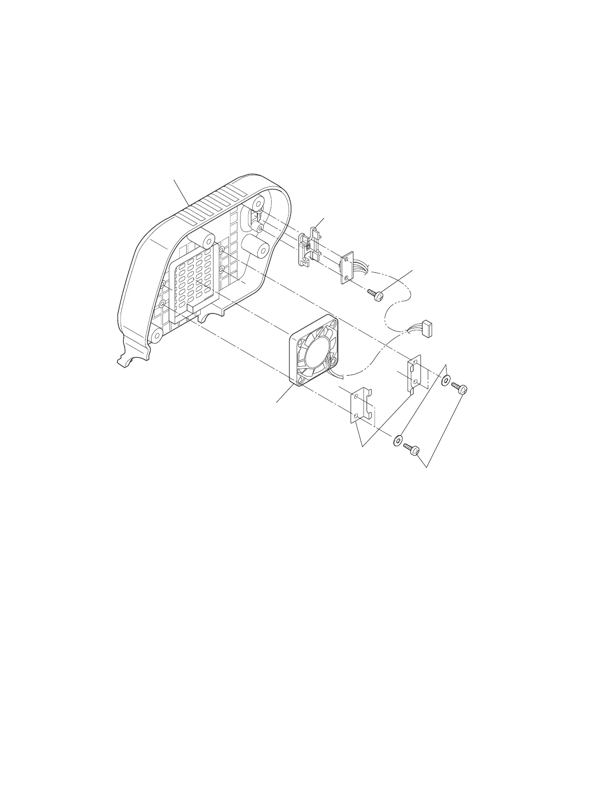
3-5-3. Fan/Dir. SW SA
1. Remove the Top Cover SA and remove the Ribbon Unit Fan SA2. Refer to Step 2 (Normal
way) in 3-5-2-(1) “Removing the Case U without detaching the Ribbon Unit (Normal way)”.
2. Remove 4 screws (BHT (#2), M3x6 (NI)) and 4 washers (M3), and detach the two Ribbon Fan
Brackets.
3. Remove 2 screws (BHT (#2), M3x6 (NI)) and detach the Fan/Dir. SW SA and the Ribbon
Direction Knob from the Ribbon Unit Cover L.
Bracket, Ribbon Fan
Knob, Ribbon Direction
BHT (#2), M3x6 (NI)
Plain, 3x8x0.5
Cover L, Ribbon Unit
SA, Fan/Dir. SW
BHT (#2), M3x6 (NI)
Note on reassembling:
• The PCB of the Fan/Dir. SW SA includes the Ribbon Winding Selection Switch which is set
according to the ribbon type to be used (inside wound or outside wound type). Leave the user’s
switch setting as it is.