SM VEHICLES
OVERHAULING AN ENGINE S 100-3 25
ASSEMBLY Contd.
41
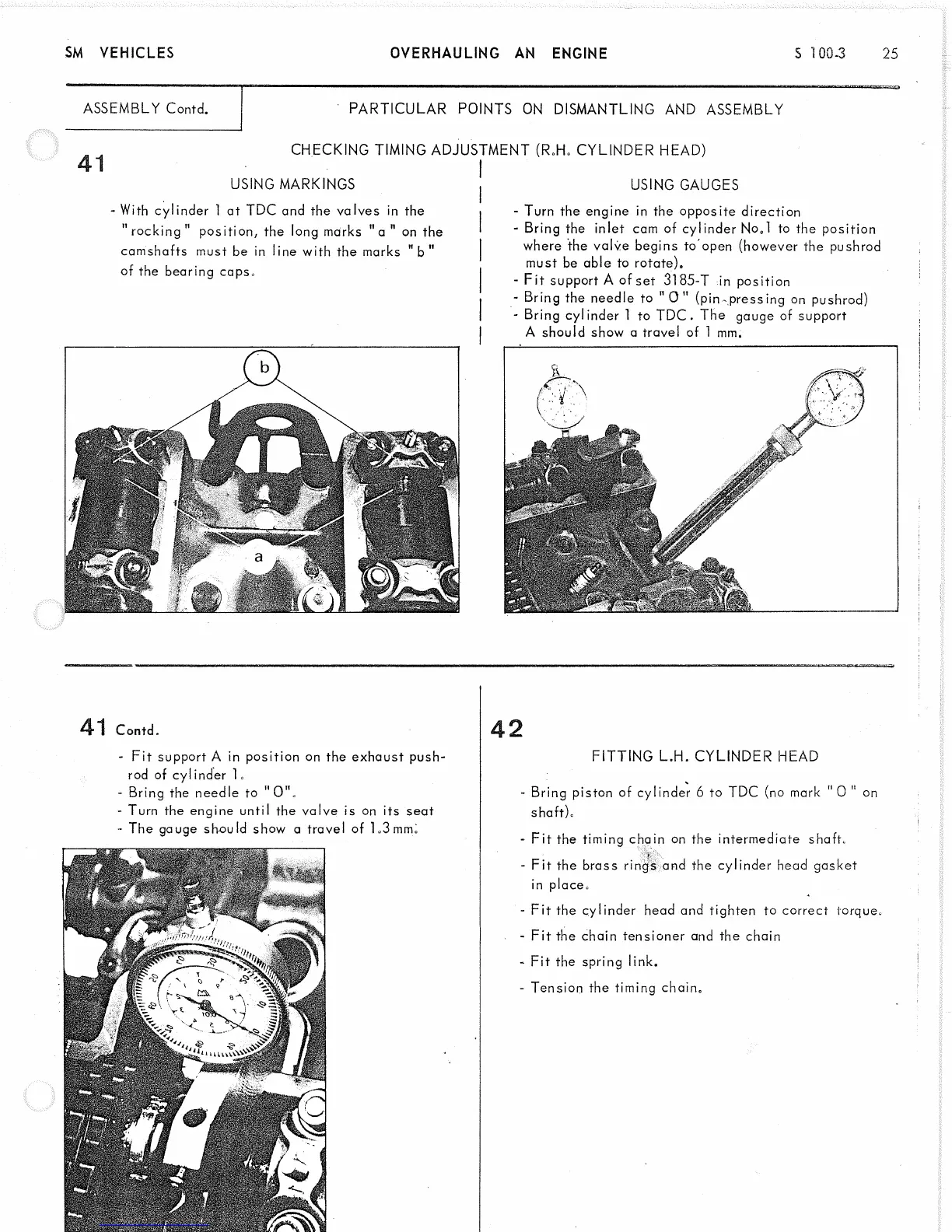
USING MARKINGS
- With cylinder 1 at TDC and the valves in the
"ro ck ing " position, the long marks " a " on the
PARTIC ULAR POINTS ON DISMANTLING AND ASSEMBLY
CHECKING TIMING ADJUSTMENT (R.H. CYLINDER HEAD)
USING GAUGES
camshafts must be in line with the marks
of the bearing caps.
b"
- Turn the engine in the opposite direction
- Bring the inlet cam of cylinder No„l to the position
where the valve begins toopen (however the pushrod
must be able to rotate).
- F it support A of set 3185-T in position
- Bring the needle to " 0 " (pin-pressing on pushrod)
- Bring cylinder 1 to TDC. The gauge of support
A should show a travel of 1 mm.
41 Contd.
- F it support A in position on the exhaust push
rod of cylinder 1«
- Bring the needle to "0"o
- Turn the engine until the valve is on its seat
- The gauge should show a travel of 1.3 mm.
42
FITTING L.H. CYLINDER HEAD
- Bring piston of cylinder 6 to TDC (no mark " 0 " on
shaft).
- F it the timing chain on the intermediate shaft.
- F it the brass rings and the cylinder head gasket
in place.
- F it the cylinder head and tighten to correct torque.
- Fit the chain tensioner and the chain
- Fit the spring link.
- Tension the timing chain.