Page 10 CI Man u al
STEP 7CS
STEP 8CS
STEP 9CS
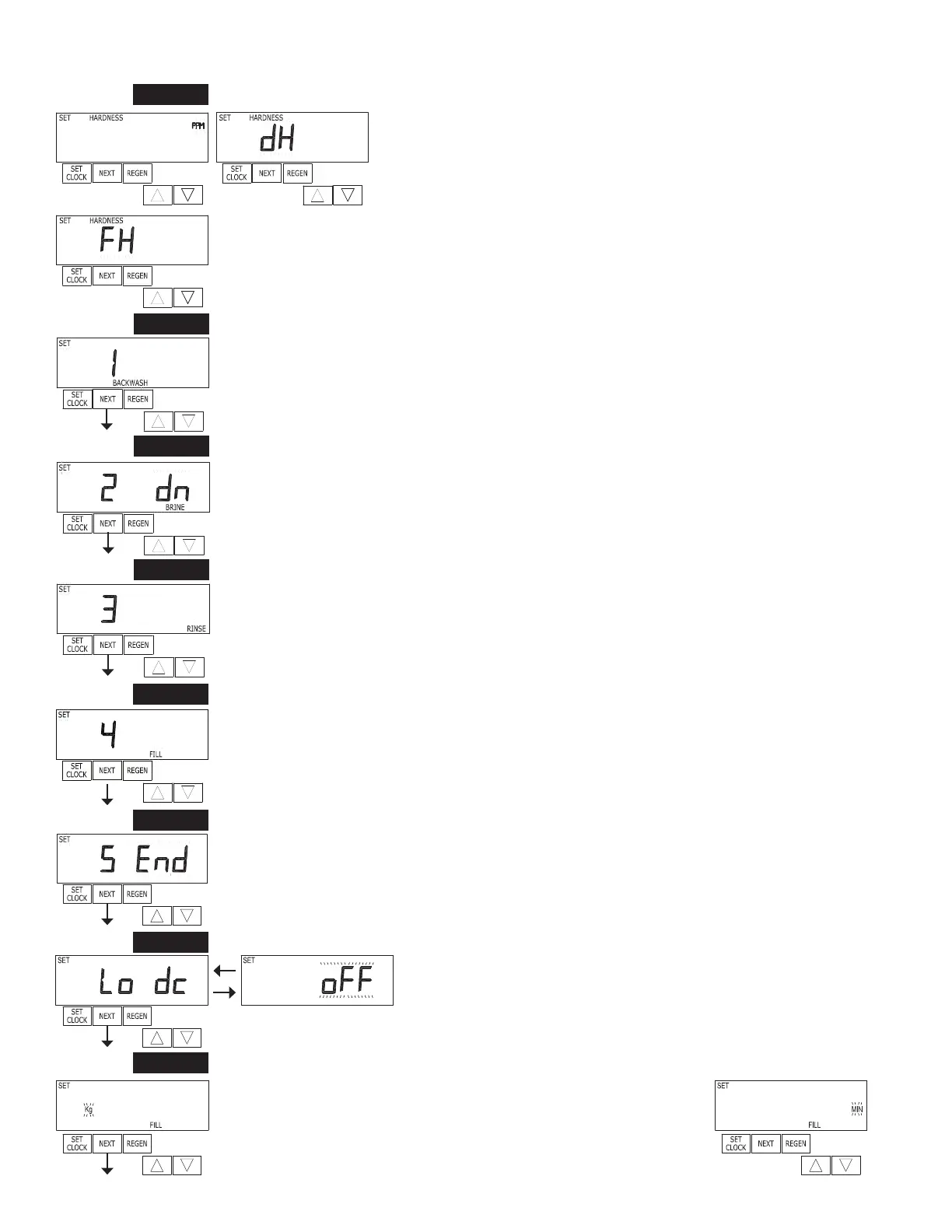
Step 7CS – Press ▲ or ▼ until BACKWASH appears. Press NEXT to go to Step 8CS. Press REGEN
to return to previous step.
STEP 10CS
STEP 11CS
Step 8CS - Press ▲ or ▼ until BRINE appears. NOTE: Prior to selecting the upfl ow regeneration
cycle, verify that the correct body, main piston, regenerant piston and stack are being used, and that the
injector plug(s) are in the correct location. Refer to the Service Manual for drawings and part numbers.
Press NEXT to go to Step 9CS. Press REGEN to return to previous step.
Step 9CS - Press ▲ or ▼ until RINSE appears. Press NEXT to go to Step 10CS. Press REGEN to
return to previous step.
Step 10CS - Press ▲ or ▼ until FILL appears. Press NEXT to go to Step 11CS. Press REGEN to
return to previous step.
Step 11CS - Press ▲ or ▼ until END appears. Press NEXT to go to Step 12CS. Press REGEN to
return to previous step.
STEP 6CS
Step 6CS – Determine the measurement to calculate volumetric capacity. The
choices are:
ppm parts per million
FH French degrees
dH German degrees
NOTE: If control is going to be used in a fi lter application none of these
settings can be used.
Press NEXT to go to Step 7CS. Press REGEN to return to previous step.
Step 13CS - Fill Units: If set as a softener, if Step 2CS is set to 1.5, and FILL is part of the
Regeneration Cycle Sequence, FILL UNITS of MIN or kg can be selected.
Press NEXT to exit OEM Cycle Sequence. Press REGEN to return to
previous step.
RETURN TO NORMAL MODE
STEP 13CS
STEP 12CS
Step 12CS - Battery operation. Set to OFF when using a wall adapter.
Set to ON when operating valve with a 12VDC deep cycle automotive-
style battery.
Press NEXT to go to Step 13CS. Press REGEN to return to previous
step.