CI Man u al Page 9
STEP 5CS
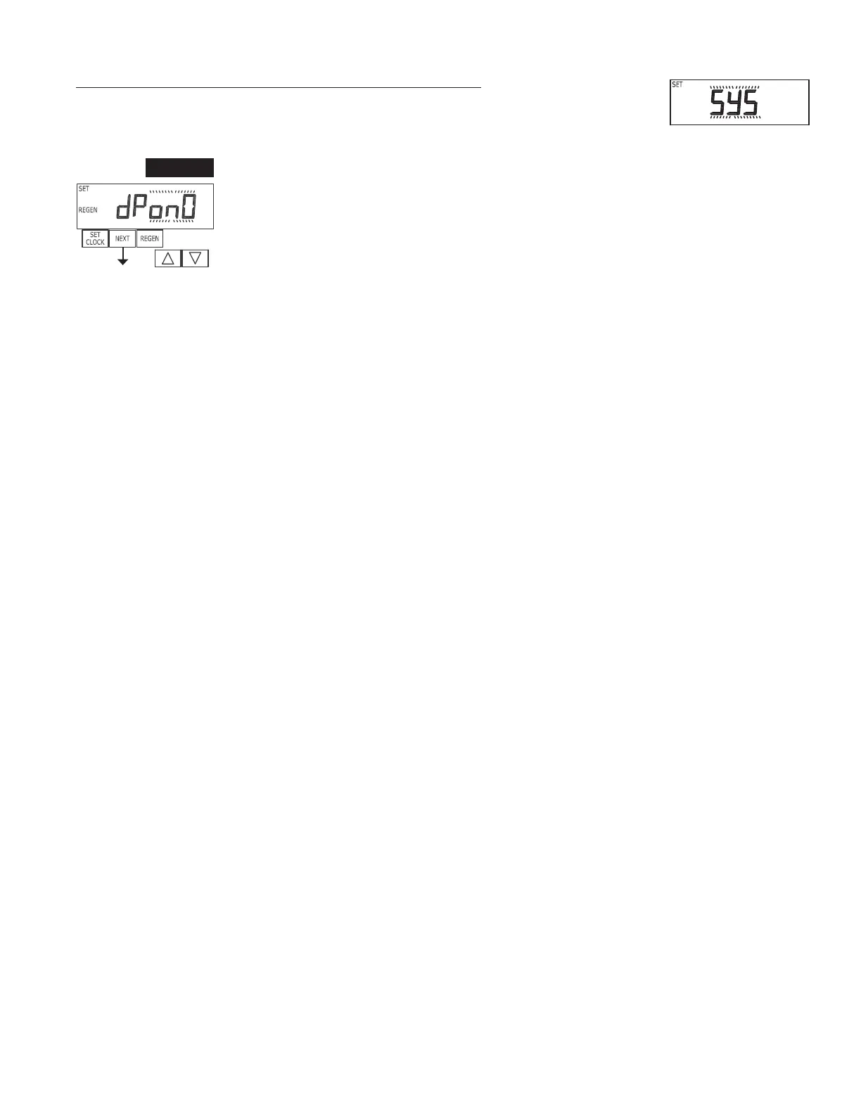
Step 5CS – Allows selection of one of the following using ▲ or ▼:
• an outside signal to initiate a regeneration;
• an outside signal to prevent or delay regeneration.
Selection only matters if a connection is made to the two pin connector labeled DP SWITCH located on
the printed circuit board. Following is an explanation of the options:
OFF - Feature not used.
NOTE: In a twin alternating system each control must have a separate dP signal or dP switch.
One dP signal or one dP switch cannot be used for both controls.
dPon0 – If the dP switch is closed for an accumulative time of 2 minutes a regeneration will be
signaled to the unit. In a twin alternating system the MAV will transition fi rst to switch units so that
the signaled unit can start regeneration. After the MAV has fully transitioned, the regeneration begins
immediately. Note: For WS1 – WS1.5 control valves programmed for twin alternating: if the dP
function “dPon0” is set, the Delayed Rinse and Fill feature is not available.
dPdEL – If the dP switch is closed for an accumulative time of 2 minutes a regeneration will occur at
the scheduled delayed regeneration time. In a twin alternating system, once the dP switch is triggered
the PC board will display REGEN TODAY and switch tanks immediately. At the Delayed Regeneration
Time, the triggered unit will then regenerate. Note: For WS1 – WS1.5 control valves programmed for
twin alternating: if the dP function “dPdEL” is set, the Delayed Rinse and Fill feature is not available.
HoLd – If the dP switch is closed a regeneration will be prevented from occurring while there is switch
closure. In a twin alternating system the regeneration of a unit can be prevented upon switch closure. If
the unit depletes the capacity down to zero, it will not be allowed to switch tanks to regenerate until the
switch is open. Note: For WS1 – WS1.5 control valves programmed for twin alternating the Delayed
Rinse and Fill feature can be set in conjunction with the “HoLd” if desired.
Press NEXT to go to Step 6CS. Press REGEN to return to previous step.
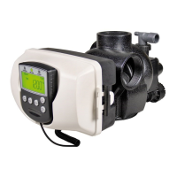
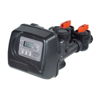
Confi guring the Control Valve to operate with Clack System Controller:
Select SYS to link the Control Valve to the Clack System Controller. For communication between
the Control Valve and the System Controller, a three-wire communication cable is required.
Press NEXT to go to Step 5CS. Press REGEN to return to previous step.