Page 12 CI Man u al
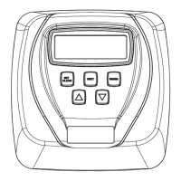
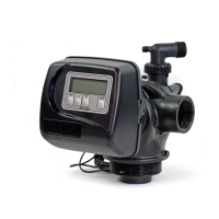
Step 7S – Set System Capacity using ▲ or ▼. See chart. The System
Capacity setting should be based on the volume of resin and Kg of salt fi ll
set in Step 6S. When using ppm, dH, or FH the system capacity and hardness
levels entered are used to determine the Volume Capacity. Press NEXT to go
to Step 8S. Press REGEN to return to previous step.
Setting Units
PPM
Kg of
CaCO
3
dH or FH M
3
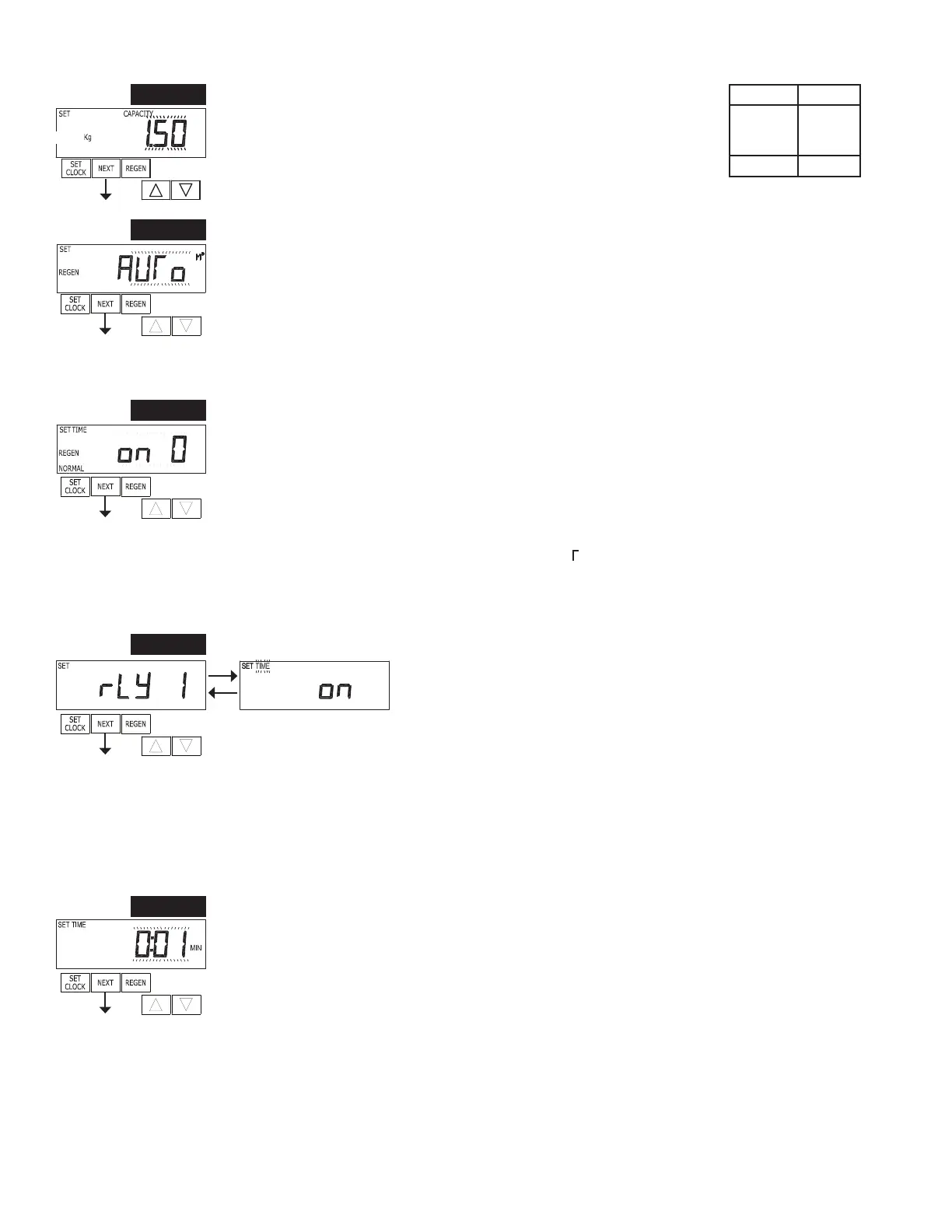
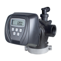
Step 8S – Set Volume Capacity using ▲ or ▼. If value is set to:
• AUTO capacity will be automatically calculated and reserve capacity will be automatically
estimated;
• oFF regeneration will be based solely on the day override set (see Installer Display/Settings Step
4I);
• a number, regeneration initiation will be based on the value specifi ed (in M
3
); or
If oFF or a number is used, hardness display will not be allowed to be set in Installer Display
Settings Step 2I & 3I. See Setting Options Table for more detail. Press NEXT to go to Step 9S. Press
REGEN to return to previous step.
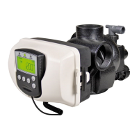
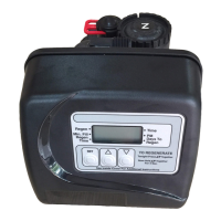
Step 9S – Set Regeneration Time Options using ▲ or ▼. If value is set to:
• NORMAL means regeneration will occur at the preset time;
• on 0 means regeneration will occur immediately when the volume capacity reaches 0 (zero); or
• NORMAL + on 0 means regeneration will occur at one of the following:
— the preset time when the volume capacity falls below the reserve or the specifi ed number of
days between regenerations is reached whichever comes fi rst; or
— immediately after 10 minutes of no water usage when the volume capacity reaches 0 (zero).
NORMAL is the default if Step 4CS is set to ALT A or ALT b, and NORMAL + on 0 is not
available. On 0 is the default if Step 2CS is set to 1.0
, and NORMAL + on 0 is not available.
This step will not appear if Step 8S is set to off or Step 4CS is set to SYS.
See Setting Options Table for more detail. Press NEXT to go to Step 10S. Press REGEN to return to
previous step.
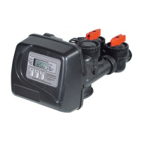
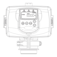
STEP 10S
Step 10S – Set Relay 1 operation using ▲ or ▼. The choices are:
• Set Time on: Relay activates after a set time at the beginning of a
regeneration cycle and then deactivates after a set period of time. The
start of regeneration is defi ned as the fi rst backwash cycle or Dn brine/Up
brine cycle, whichever comes fi rst.
• Set L Softening on: Relay activates after a set volume has been used
while in service, then deactivates after the meter stops registering fl ow and the set time period has
expired.
• Set L Softening Regen on: Relay activates after a set volume has been used while in service or
during regeneration, then deactivates after the meter stops registering fl ow and the set time period
has expired.
• Set Off: If set to Off, Steps 11S and 12S will not be shown.
Press NEXT to go to Step 11S. Press REGEN to return to previous step.
STEP 9S
STEP 8S
STEP 7S
Step 11S – Set Relay 1 Actuation Time or Liters using ▲ or ▼. The choices are:
• Relay Actuation Time: After the start of a regeneration the amount of time that should pass prior
to activating the relay. The start of regeneration is defi ned as the fi rst backwash cycle or Dn brine
cycle, whichever comes fi rst. Ranges from 1 second to 200 minutes.
• Relay Actuation Liters: Relay activates after a set number of Liters has passed through the meter
when the valve is in the Service mode. Ranges from 1 to 200 Liters.
Press NEXT to go to Step 12S. Press REGEN to return to previous step.
STEP 11S