CI Man u al Page 7
Step 4CS – Allows selection of one of the following using ▲ or ▼:
• the Control Valve to have no hard water bypass;
• the Control Valve to act as an alternator; or
• the Control Valve to have a separate source during the regeneration cycle; or
• the Control Valve to operate with the Clack System Controller.
Select OFF when none of these features are used.
This display will not appear if 1.0
was selected in Step 2CS.
Only use Clack No Hard Water Bypass Valves or Clack Motorized Alternating Valves (MAV) with
these selections. Clack No Hard Water Bypass Valves (1” or 1.25” V3070FF or V3070FM) are not
designed to be used with the alternator or separate source functions.
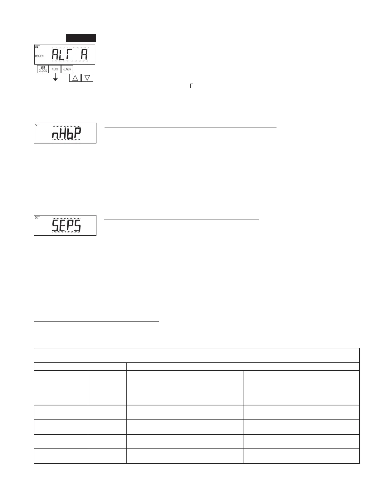
STEP 4CS
Selecting the Control Valve to act as an alternator:
Software Rev Level 320.0 and higher = Use 3-wire Interconnect Cable for all communication between units.
Software Rev Level 319.5 and lower = Use 2-wire Interconnect Cables for twin alternators with independent fl ow meters.
Prior to starting the programming steps, connect the interconnect cable to each control valve board’s three pin connector labeled ‘COMM
CABLE’. Also connect the meter cord to either control valve to the three pin connector labeled ‘METER’.
Softener Valve Programming Steps
OEM Cycle Sequence Step 4CS
Set to ALT A
Connect ALT A valve to the MAV’s A port and
connect the MAV’s two pin wire connector to the
two pin connector labeled “DRIVE” on the ALT
A valve
Set to ALT b
Connect ALT b valve to the MAV’s B port. No
connections between the ALT b valve and the
MAV are made.
Softener System
Setup
Step 7S Set Volume Capacity Set Volume Capacity
Softener System
Setup
Step 8S Set to ‘AUTO’ Set to ‘AUTO’
Softener System
Setup
Step 9S Set regeneration time option to ‘on 0’. Set regeneration time option to ‘on 0’.
Installer Display
Setting
Step 4I Set Day Over ride to “oFF” Set Day Over ride to “oFF”
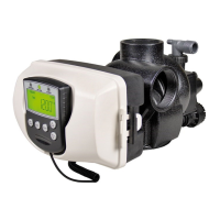
Confi guring the Control Valve for No Hard Water Bypass Operation:
Select nHbP for control operation. For no hard water bypass operation the three wire communication
connector is not used.
Selection requires that a connection to MAV or a Clack No Hard Water Bypass Valve is made to the
two pin connector labeled MAV located on the printed circuit board. If using a MAV, the A port of the
MAV must be plugged and the valve outlet connected to the B port. When set to nHbP the MAV will
be driven closed before the fi rst regeneration cycle that is not FILL or SOFTENING or FILTERING,
and be driven open after the last regeneration cycle that is not FILL.
NOTE: If the control valve enters into an error state during regeneration mode, the no hard water
bypass valve will remain in its current state until the error is corrected and reset.
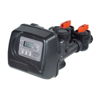
Confi guring the Control Valve for Separate Source Operation:
Select SEPS for control operation. For separate source operation the three wire communication
connector is not used.
Selection requires that a connection to a Clack Motorized Alternator Valve (MAV) is made to the
two pin connector labeled MAV located on the printed circuit board. The C port of the MAV must be
connected to the valve inlet and the A port connected to the separate source used during regeneration.
The B port must be connected to the feed water supply.
When set to SEPS the MAV will be driven closed before the fi rst regeneration cycle, and be driven
open after the last regeneration cycle.
NOTE: If the control valve enters into an error state during regeneration mode, the MAV will remain
in its current state until the error is corrected and reset.