M 3..7
22
EN
Installation
ing width of ≥3mm per phase must be provided at the installation end.
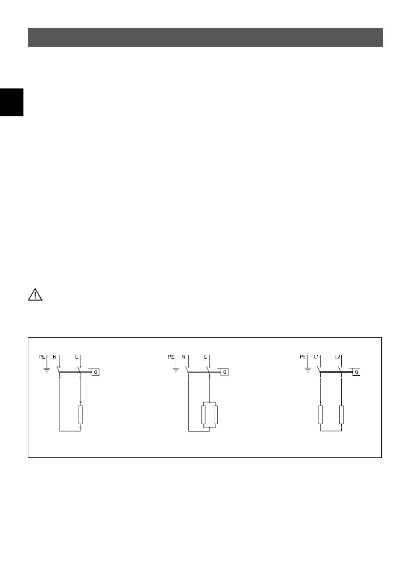
b. Connect the connecting pipe via a junction box to the mains, as shown in the circuit dia-
gram.
Alternatively:
4. Connection to a permanently installed cable:
a. Note that according to VDE 0700, an all-pole disconnecting device with a contact open-
ing width of ≥3 mm per phase should be provided at the installation end.
b. The cross-section of the cable must meet the requirements of the minimal cross-section,
as mentioned in chapter “Technical specifications“. The maximum applicable cross-sec-
tion is 6 mm
2
.
c. Open the cover.
d. Dismount the pre-installed connection cable.
e. Route the permanently installed cable through the grommet and connect it as shown in
the circuit diagram. Make sure that the grommet fits tightly around the cable to ensure
optimal protection against water.
f. Refit the cover on the appliance.
The earth conductor must be connected!
Fig. 6:
“Circuit diagram”
M 3, M 4 (230 V) M 6 (230 V)
M 7 (400 V)
 Loading...