88 CMS5 CMS5 89
Owner’s Manual
English
Please follow these connection diagrams carefully
6. WIRE CONNECTIONS
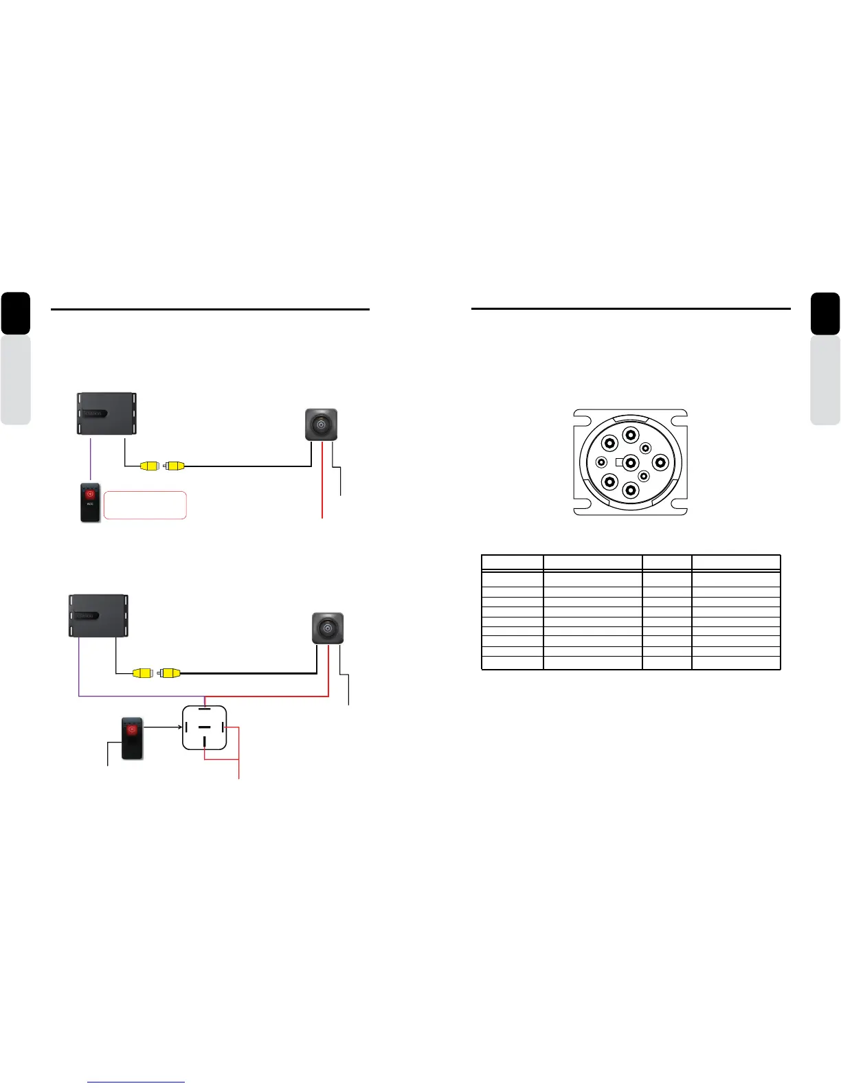
Rear Vision Camera Connection Diagram
CC510 or any backup Camera-
CMS5 Black Box
12 Volt Switched (Ignition)
Ground
RCA Video Output from Camera to dedicated
Camera Input on CMS5 Black Box
Connect Purple Camera (+)
Trigger Wire to a 12V +
Switch
When switched ON it will provide
a +12V to the Purple 12V (+)
Camera Input Trigger to the CMS5
Black Box
Option: 1
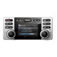
Rear Vision Camera Connection Diagram
RCA Video Output from Camera to dedicated Camera Input on
CMS5 Black Box
CC510 or any back-up Camera
Ground
30
86
85
87A
87
12 Volt Switched (Ignition)
Ground
CMS5 Black Box
Camera
Input
Option: 2
Owner’s Manual
English
Please follow these connection diagrams carefully
6. WIRE CONNECTIONS
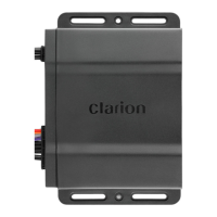
NOTE:
This J1939 CAN Connector contains insulated twisted wires that are
Connected by terminating resistors on the dedicated CAN on the main
PCB of the CMS5 Black Box.
View: Front of J1939 Connector
J1939 Connector
PIN NUMBER NAME GAUGE COLOR
A CAN B - 20 WHITE
B CAN B + 20 PURPLE
C CAN HIGH 20 YELLOW
D CAN LOW 20 GREEN
E CAN - DRAIN 20 BLACK
F NOT USED
G NOT USED
H NOT USED
J NOT USED
Only use this J1939 Connector to compatible Multi-Function Displays (MFD)
ON
OFF
CAMERA
A
B
C
D
E
G
F
H
J