57
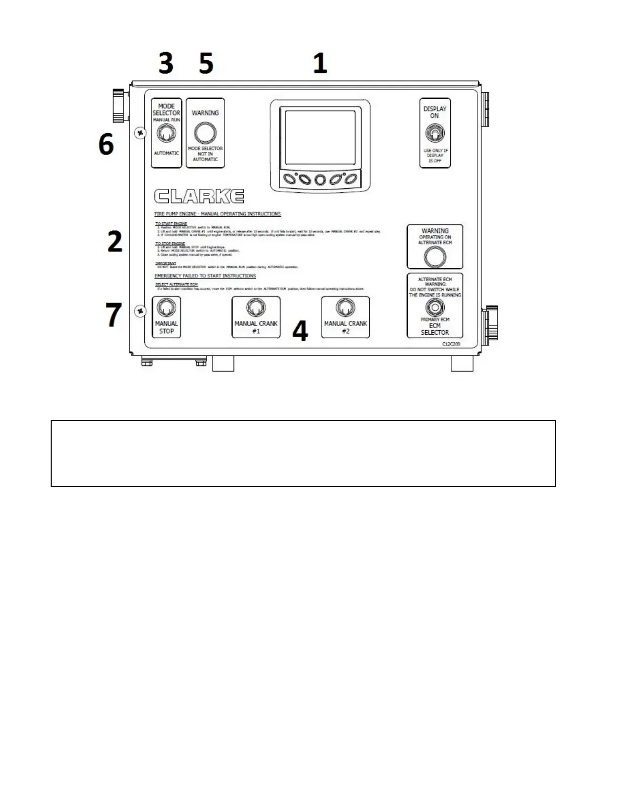
Figure #28 – Clarke Instrument Panel
1 – Powerview Gauge
2 – Emergency operating instructions 5 – Warning Light
3 – Automatic / Manual Mode Selector Switch 6 – VSPLC / VSSLC wiring harness
4 – Manual Crank Controls 7 – Manual Stop
15.2.3.3 Adjustments
There are no field adjustments; other than fine
tuning the throttle adjustment when setting the
engine rated speed with pump operating at
rated flow (Section 3.6 of this manual).
15.3 ENGINE SYSTEMS
15.3.1 Electrical System
15.3.1.1 Wiring Diagram
Refer to Figure #29 for the wiring diagram
that shows the additional circuits added to
a PLD equipped engine. Note, for the
standard engine wiring diagram refer to the
“SERVICE” tab at www.clarkefire.com.
 Loading...