29
Tranquility
®
Digital (DXM2)—Troubleshooting Guide
Rev.: 10 March, 2015
www.climatemaster.com
Refrigeration Troubleshooting
A-H
P1
Alarm
Relay
Comp
Relay
O
Y1
Y2
W
G
C
R
AL1
24Vdc
EH1
EH2
P6
R
C
Off On
JW3
A
OVR
ESD
C
R
NSB
AL2
JW1
Acc1
Relay
Acc2
Relay
H
COM
NC1
NO1
COM
NC2
NO2
P3
CO
RV
RV
LT1
LT1
LT2
LT2
LP
LP
HP
HP
P7
Status
Fault
R
R
CC
CCG
CO
S1
S2
1
12
1
4
Factory Use
(240Vac)
Com
N.O.
Fan Enable
5 1/2"
7"
6 1/2"
5"
Use 4 mounting screws
#6 sheet metal screw 1” long
1.5
3/8” standoff
Factory low
voltage molex
connection for
unit harness
Factory low
voltage molex
connection for
electric heat
harness
Micro
U1
Off On
P2
COH
COM
AO2
P11
Gnd
T1
P10
T2 T2 T3 T3 T4 T4
T5
P9
T5
T6 T6
A0-1 A0-2
Off On
S3
RV
Relay
CCH
Relay
Test
P5
B-
Gnd
P4
A+ 24V
(240Vac)
Fan Speed
N.O.
N.C.
12V
OUT
Gnd
P8
IN
NC
P12
Note: There is only
one T1 connection
1 2 3 4
1 2 3 4 5 6 7 8
1 2 3 4 5 6 7 8
AO1
Gnd
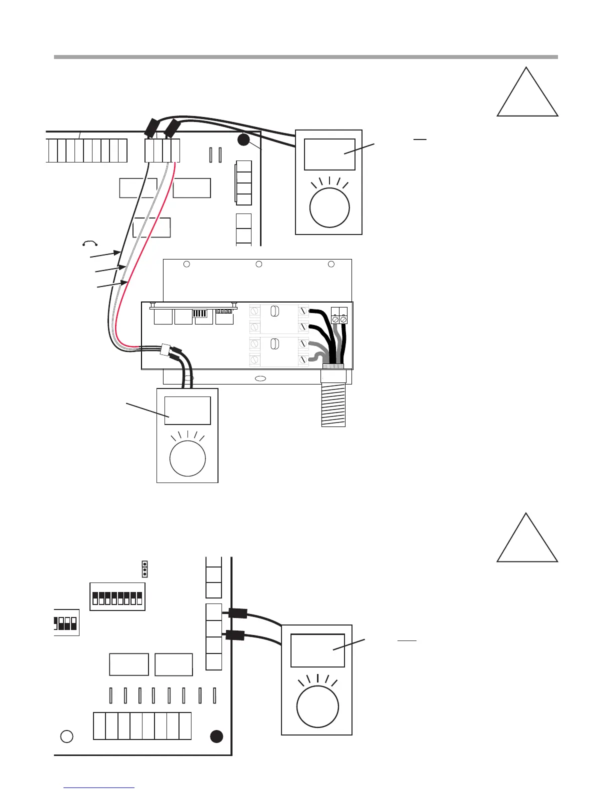
0.5-10 VDC with Pump Running
Note: P11 is the DXM2’s
output signal is to the pump.
ON
OFF
ON
OFF
1234
P1
L1
L2
L3
L4
P2
Verify that 24 VDC
is going to auxiliary
control board.
P1
Alarm
Relay
Comp
Relay
O
Y1
Y2
W
G
C
R
AL1
24Vdc
EH1
EH2
P6
R
C
Off On
JW3
A
OVR
ESD
C
R
NSB
AL2
JW1
Acc1
Relay
Acc2
Relay
H
COM
NC1
NO1
COM
NC2
NO2
P3
CO
RV
RV
LT1
LT1
LT2
LT2
LP
LP
HP
HP
P7
Status
Fault
R
R
CC
CCG
CO
S1
S2
1
12
1
4
Factory Use
(240Vac)
Com
N.O.
Fan Enable
5 1/2"
7"
6 1/2"
5"
Use 4 mounting screws
#6 sheet metal screw 1” long
1.5
3/8” standoff
Factory low
voltage molex
connection for
unit harness
Factory low
voltage molex
connection for
electric heat
harness
Micro
U1
Off On
P2
COH
COM
AO2
P11
Gnd
T1
P10
T2 T2 T3 T3 T4 T4
T5
P9
T5
T6 T6
A0-1 A0-2
Off On
S3
RV
Relay
CCH
Relay
Test
P5
B-
Gnd
P4
A+ 24V
(240Vac)
Fan Speed
N.O.
N.C.
12V
OUT
Gnd
P8
IN
NC
P12
Note: There is only
one T1 connection
1 2 3 4
1 2 3 4 5 6 7 8
1 2 3 4 5 6 7 8
AO1
Gnd
24 volts DC
First stage auxiliary heat
Note: Verify second stage auxiliary
heat by moving one prod to EH2
Note: If dipswitch #6 in bank S1 is
turned OFF, the relays will rapidly turn
on and off and will burn up the relays.
Note: On Splits, check this on the AXM
Board in the Air Handler.
Black
White
Red
Auxiliary Heat Check
A-I
Checking Pump Output
A-J
Note: White wire is
connected to A02.