35
Tranquility
®
Digital (DXM2)—Troubleshooting Guide
Rev.: 10 March, 2015
www.climatemaster.com
P1
Alarm
Relay
Comp
Relay
O
Y1
Y2
W
G
C
R
AL1
24Vdc
EH1
EH2
P6
R
C
Off On
JW3
A
OVR
ESD
C
R
NSB
AL2
JW1
Acc1
Relay
Acc2
Relay
H
COM
NC1
NO1
COM
NC2
NO2
P3
CO
RV
RV
LT1
LT1
LT2
LT2
LP
LP
HP
HP
P7
Status
Fault
R
R
CC
CCG
CO
S1
S2
1
12
1
4
Factory Use
(240Vac)
Com
N.O.
Fan Enable
5 1/2"
7"
6 1/2"
5"
Use 4 mounting screws
#6 sheet metal screw 1” long
1.5
3/8” standoff
Factory low
voltage molex
connection for
unit harness
Factory low
voltage molex
connection for
electric heat
harness
Micro
U1
Off On
P2
COH
COM
AO2
P11
Gnd
T1
P10
T2 T2 T3 T3 T4 T4
T5
P9
T5
T6 T6
A0-1 A0-2
Off On
S3
RV
Relay
CCH
Relay
Test
P5
B-
Gnd
P4
A+ 24V
(240Vac)
Fan Speed
N.O.
N.C.
12V
OUT
Gnd
P8
IN
NC
P12
Note: There is only
one T1 connection
1 2 3 4
1 2 3 4 5 6 7 8
1 2 3 4 5 6 7 8
AO1
Gnd
18-31.5
Volts AC
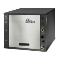
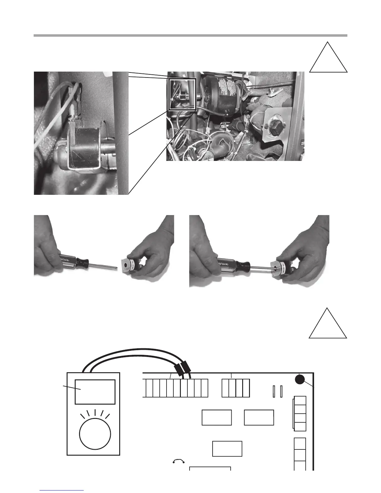
Checking Reversing Valve at DXM2
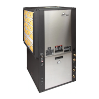
A-U
Verifying 24V at Reversing Valve
A-T
Verify 24V at reversing valve when calling for cooling
To check the solenoid’s magnetic pull, begin by pulling solenoid off of reversing valve. Then energize solenoid and place a
metal screw driver in solenoid. You should feel the screw driver being pulled by the magnetic eld.