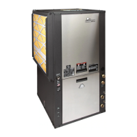
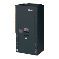
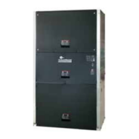
EasyManua.ls Logo

ClimateMaster Tranquility TSM Series User Manual

ClimateMaster Tranquility TSM Series
88 pages
To Next Page IconTo Next Page
Page #1 background imageLoading...
Page #1 background image
Tranquility
®
Vertical Stack
(TSM/TSL) Series
Vertical Stack
Water-Source
Heat Pumps
Installation, Operation
& Maintenance
97B0001N14
Rev.: January 18, 2021
Table of Contents
General Information – Inspection 3
C, D, & E Cabinet Series Model Nomenclature 4-6
TSM/TSL Chassis Series Model Nomenclature 7
Accessory Nomenclature 8-10
Physical Data 11-13
Pre-Installation Information 14
Riser & Cabinet Installation 15-21
Leader/Follower Cabinet Installation 22
C & D Cabinet Slot Dimensions
and Riser Arrangements 23
E Cabinet Slot Dimensions and Riser Arrangements 24
80” & 88” Cabinet Congurations 25
Supply Grille Installation 26
Typical Cabinet with “L” Panel Installation 27
Typical Cabinet with “G” Panel Installation 28
Typical Cabinet with “G” Panel Installation – Recessed 29
Drywall Openings 30-31
Cabinet with “G” Panel Frames 32
Water-Loop Heat Pump Applications 33
Ground-Loop Heat Pump Applications 34
Ground-Water Heat Pump Applications 35-36
Water Quality Standards 37
Electrical Wiring - Line Voltage 38
ECM-CV Blower Performance Data 39
Blower Performance Data –TSM 40-46
Blower Performance Data – TSL 47-53
Hybrid Blower Motor Correction Table 53
Electrical Wiring - Low Voltage 54
Thermostat Installation 55
Chassis Pre-Installation 56
Hose Kit and Chassis Installation 57-59
Start-Up Preparation 60
CXM Control 61
DXM2 Control 62-63
Safety Features - CXM/DXM2 Controls 64-65
Unit Commissioning and Operating Conditions 66
Unit and System Checkout 67
Unit Start-Up Procedures 68
Unit Operating Pressures and Temperatures 69-71
Coax Water Pressure Drop 72
Start-Up Log Sheet 73
Preventive Maintenance 74
Functional Troubleshooting 75
Performance Troubleshooting 76
Wire Harness Part Numbers 77-83

Questions and Answers:

ClimateMaster Tranquility TSM Series Specifications

General IconGeneral
TypeWater Source Heat Pump
RefrigerantR-410A
Compressor TypeScroll
Stages of OperationSingle Stage
ConfigurationVertical or Horizontal
Voltage Options208/230V, 460V, 575V

Summary

General Information – Inspection

Safety

General safety information, warnings, and definitions for handling equipment safely.

Inspection Process

Procedures for inspecting received equipment against shipping documents and for damage.

C Cabinet Series Model Nomenclature – TSM

Unit Size

Defines the unit size for TSM cabinets based on model nomenclature.

Voltage

Specifies voltage options available for TSM cabinets.

D Cabinet Series Model Nomenclature – Heat Pump – TSL

Unit Size

Defines the unit size for TSL cabinets based on model nomenclature.

Voltage

Specifies voltage options available for TSL cabinets.

E Cabinet Series Model Nomenclature – TSL Hybrid

Unit Size

Defines the unit size for TSL Hybrid cabinets based on model nomenclature.

Voltage

Specifies voltage options available for TSL Hybrid cabinets.

TSM/TSL Chassis Series Model Nomenclature

Chassis Options

Configuration options for the unit chassis based on model nomenclature.

Controls

Details on available control systems for the chassis.

Accessory Nomenclature

Return Air Panel "G" Style

Nomenclature details for the 'G' style return air panel accessory.

Hose Kit

Nomenclature details for the accessory hose kit.

Accessory Nomenclature, Cont'd.

Supply Air Grille

Nomenclature details for the supply air grille accessory.

Accessory Nomenclature, Cont'd.

Riser

Nomenclature details for the riser accessory.

Physical Data – TSM

Motor & Blower

Physical data for TSM unit motors and blowers.

Weight

Physical data related to TSM unit weight.

Pre-Installation Information

Storage

Guidelines for storing equipment prior to installation.

Prepare Cabinet for Installation

Steps to prepare the cabinet before installation.

Riser and Cabinet Installation

Core Drilling For Vertical Riser Stack

Information and considerations for core drilling for riser stacks.

Cabinet Installation

Procedures for installing the unit cabinet.

Riser and Cabinet Installation, Cont'd.

Riser Installation When Risers are Shipped Separately

Steps for installing risers that were shipped separately.

Riser and Cabinet Installation, Cont'd.

Supply and Return Stack

Guidelines for supply and return riser stack configurations.

Drywall Installation

Instructions for drywall installation around the unit.

Leader/Follower Cabinet Installation

Notes

Important notes regarding leader/follower cabinet installation.

C & D Cabinet Slot Dimensions and Riser Arrangements

Notes

Detailed notes on C & D cabinet slot dimensions and riser arrangements.

80" & 88" Cabinet Configurations

Air Flow Configuration

Diagrams illustrating airflow configurations for 80" and 88" cabinets.

Supply Grille Installation

Supply Grille Installation

Steps for installing the supply grille into the cabinet.

Typical Cabinet with “L” Panel Installation

Frame Installation

Instructions for installing the cabinet frame for L-panel units.

Typical Cabinet with “G” Panel Installation

Notes

Detailed notes for installing cabinets with G-panel.

Drywall Openings

Drywall Openings for sizes 15-18 and G Panel on floor

Specific drywall opening dimensions for 15-18 cabinets and G panels.

Water-Loop Heat Pump Applications

Commercial Water Loop Applications

Overview of commercial water loop heat pump systems.

Water Quality Standards

Guidelines for water quality in loop systems.

Ground-Loop Heat Pump Applications

Piping Installation

Guidelines for installing ground loop piping materials.

Ground-Water Heat Pump Applications

Open Loop

Details and considerations for open loop ground water systems.

Flow Regulation

Methods for regulating water flow in the system.

Electrical Wiring – Line Voltage

Blower Speed Selection

Instructions for selecting blower speed for PSC and ECM motors.

ECM-CV Blower Performance Data

Table 5: TSM/TSL with ECM-CV Motor

Blower performance data for ECM-CV motors across models.

Blower Performance Data – TSM09

Table 5a

TSM09 blower performance data based on speed tap and static pressure.

Electrical Wiring – Low Voltage

Thermostat Connections

Guidance on connecting thermostats to the CXM/DXM2 board.

Low Water Temperature Cutout Selection

Setting low water temperature limits via jumper selection.

Thermostat Installation

Installation of Optional Wall-Mounted Thermostat

Instructions for installing optional wall-mounted thermostats.

Chassis Pre-Installation

Figures 15-18

Diagrams illustrating chassis components and connections.

Hose Kit and Chassis Installation

Step 1

First step in installing the hose kit and chassis.

Hose Kit and Chassis Installation, Cont'd.

Step 4: Chassis Installation

Final steps for installing the chassis into the unit.

Unit Start-Up Preparation

System Cleaning and Flushing

Procedures for cleaning and flushing the system before start-up.

Flush risers as follows

Detailed steps for flushing the riser piping.

CXM Control

Field Selectable Inputs

Selecting operational modes and inputs for the CXM control.

Field Configuration Options

Configuring CXM control settings via jumpers and DIP switches.

DXM2 Control

Field Selectable Inputs

Selecting operational modes and inputs for the DXM2 control.

DIP Switches

Configuring DXM2 control settings using DIP switches.

Safety Features – CXM/DXM2 Controls

Anti-short cycle protection

Safety feature protecting the compressor from short cycling.

High pressure switch

Safety feature protecting against high refrigerant pressures.

Water coil low temperature (LT1)

Safety feature protecting against low water coil temperatures.

Unit Commissioning and Operating Conditions

Table 11: Building Commissioning Limits

Limits for initial unit commissioning based on environmental conditions.

Table 12: Unit Operating Limits

Maximum and minimum operating ranges for the unit.

Unit and System Checkout

SYSTEM CHECKOUT

Checklist for verifying system components and operation.

UNIT CHECKOUT

Checklist for verifying unit components and operation.

Unit Start-Up Procedures

steps 1-12

Step-by-step procedure for starting up the unit.

Unit Operating Pressures and Temperatures

Table 14A: TSM/TSL09

Operating pressures and temperatures for TSM/TSL09 models.

Table 14B: TSM/TSL12

Operating pressures and temperatures for TSM/TSL12 models.

Preventive Maintenance

Water Coil Maintenance (Direct ground water applications only)

Maintenance for water coils in direct ground water systems.

Filters

Maintenance procedures for inspecting and cleaning filters.

Compressor

Maintenance checks for the compressor.

Functional Troubleshooting

Table

Troubleshooting table for CXM/DXM2 control faults.

Performance Troubleshooting

Table

Table detailing common performance issues and their causes.

Wire Harnesses for 09-12 ECM-CV Motor

Notes

Important notes and part numbers for wire harnesses.

Wire Harnesses for 09-36 PSC Motor

Notes

Important notes and part numbers for wire harnesses.

Troubleshooting Form

Form fields

Fields for recording unit data during troubleshooting.

Warranty

Grant of Limited Express Warranty

Details of the limited express warranty coverage.

Limitation of Remedies

Limitations on buyer's remedies for warranty claims.

Revision History

Table

Record of document revisions with dates and actions.

Related product manuals