Compact controller ER 2022S and ER 2022SA
8. Configuration
8. 3 Generator ”Pro”
slope
1
2
°C/min mm:ss
°C/hour hh:mm
°C/day dd:hh
s=seconds; m=minutes; h=hours; d=days
Unit of ramp slope in °C per time unit, or format of segment times
for program controller/generator.
Value of slope for ramp function
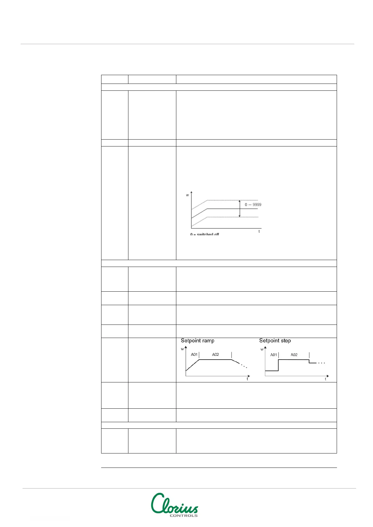
Tolerance
band
For a program controller/generator and ramp function, the
process value can be monitored by applying a tolerance band
around the setpoint profile.
If the upper or lower limit is infringed, a tolerance limit signal is
generated, which is internally processed or produced via an
output.
Example:
Signal is produced when
process value is 20 °C
larger or smaller than
setpoint.
toLP=40
Processing the tolerance
limit signal, see:
Chapter 8.5 Outputs “OutP”
Chapter 8.6 Binary functions “binF”
start
start at the
process
Defines whether the program starts with the first program
setpoint or whether the present process value is accepted as the
first program setpoint.
Defines the response to over/under range
to power-
automatic start
Defines whether the program starts on connecting the supply
voltage.
The “Cyclic” setting has the effect of continuously repeating the
program.
Set point
repeat
Step
the most
recent set
active
If active, the process is controlled to the most recent program
setpoint after the program has ended.
Delays the program start by an adjustable time.
“Strt” is shown in the lower display.
contacts
SK2
SK3
The four control contacts can be activated in the basic status
(when the program is not running).
NOTE: Factory settings shown with BOLD text