Compact controller ER 2022S and ER 2022SA
8. Configuration
8.8 Timer “tFct”
tFct: Timer
Timme-dependent control actions can be conducted with the help of
the timer. The timer signal (timer 1+ 2) shows whether the timer is
active. It can be output via the binary outputs or processed internally.
The timers are started or canceled via the binary functions.
v Chapter 8.6 “Binary functions “binF””
The current timer run times can be viewed at the operator level (process
data).
Timer 1 tF1 ➔
Symbol Value/selection Description
Function
Fnct
0
1
2
3
4
5
6
with timer running: timer signal=1 (signal is
active) / unit of time: hh:mm
with timer running: timer signal=0 (signal is
inactive) / unit of time: hh:mm
tolerance band / unit of time: hh:mm
with timer running: timer signal=1 (signal is
active) / unit of time: mm:ss
with timer running: timer signal=0 (signal is
inactive) / unit of time: mm:ss
tolerance band / unit of time: mm:ss
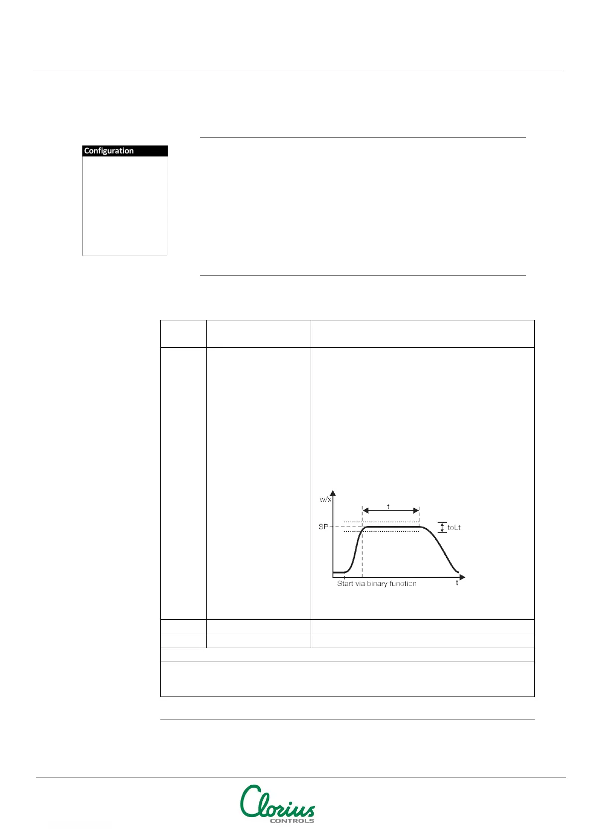
Function: “Tolerance band”
Time is running when the process value has reached
a tolerance band around the setpoint.
Timer signal=1 (signal is active) while time is running.
Time input (unit of time, see “Function”)
User data (setup program)
Up to eight parameters from various levels can be shown under User data (operator level)
on the instrument and edited. The symbols for these parameters (shown in the lower
display) must be assigned by the user himself.
NOTE: Factory settings shown with BOLD text
Controller
Generator
Limit comparators
Outputs
Binary functions
Display
Timer