MAN.234 Rev.6 ENG - Use and maintenance manual S19HD page 30 of 126
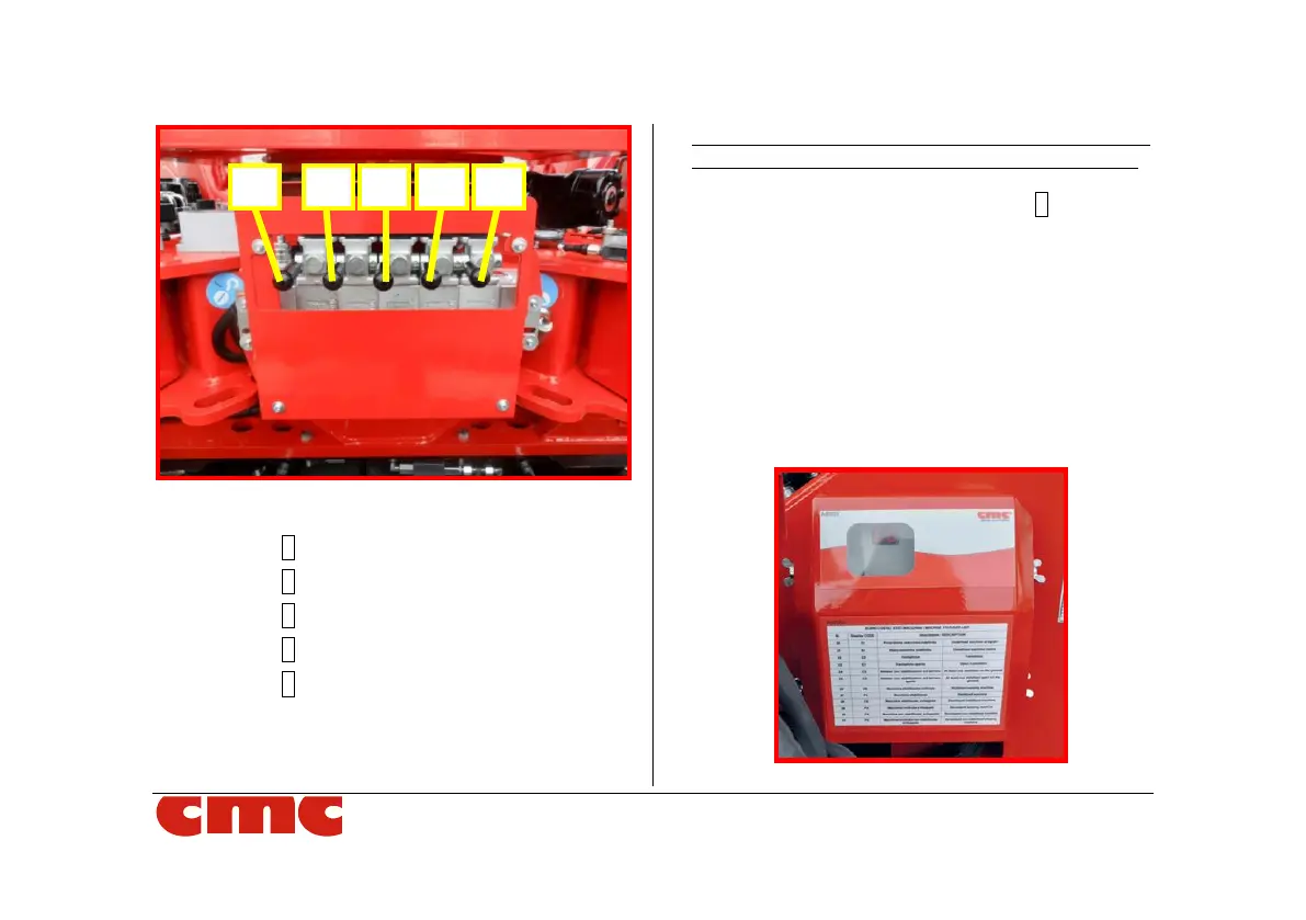
Picture 13: outriggers control station.
• lever 1 for left rear outrigger;
• lever 2 for right rear outrigger;
• lever 3 for left front outrigger;
• lever 4 for right front outrigger;
• lever 5 for tracks: it, upward, restricts the
tracks and downward widen them.
Each lever, moved upward, runs the lifting of the
outrigger and if moved downward the lowering of it.
The “dead man” outriggers button 9 (Picture 4)
must be held pressed together with the levers of
outriggers control station to stabilize or destabilize.
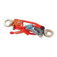
3.3.2 Display
The display (Picture 14), placed at left side of the
machine frame, near the outriggers control station,
shows the machine status when there is any
anomaly or system error.
Picture 14: display.