MAN.234 Rev.6 ENG - Use and maintenance manual S19HD page 42 of 126
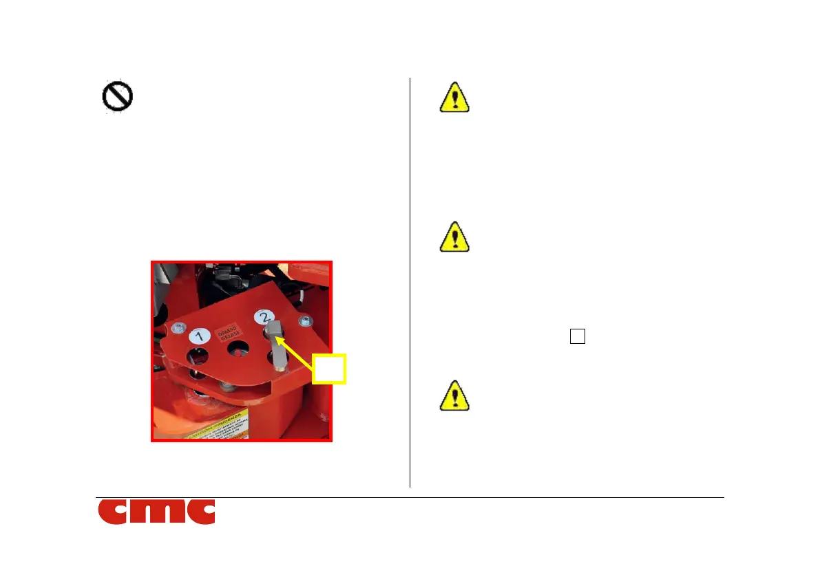
It is forbidden, and unnecessary, to com-
pletely remove the pins from their seat.
7. rotate the stabilizer up to the hole on the sta-
biliser and the hole on the chassis plate are
coaxial (choosing the inside for the narrow
area and the outside for the wide area);
8. reinsert the pin into hole selected;
9. repeat these operations for the other three
outriggers.
Picture 18: insertion of outrigger pin.
The tracks should remain extended to max-
imum width for improved stability and in-
creased ground clearance. Note that both the
width and the height of the MEWP are af-
fected by adjusting track extension. One
track can be adjusted to level the chassis
when travelling over uneven terrain, but trav-
elling across a slope should be avoided.
Check the status of cleanliness and integrity
of the limit switches in-built in the stabilizers
(cursor, bracket, spring, etc.) before the op-
erations described above.
10. proceed to the automatic stabilization
through the lever 11 (Picture 8) on radio con-
trol station or to manual stabilization by the
outriggers control station (par. 3.3.1).
IT IS ESSENTIAL TO CARRY OUT THE
STABILIZATION OPERATIONS BY
OPERATING ON ALL FOUR LEVERS
SIMULTANEOUSLY. Once the feet will all
have touched the ground, it will be possi-
ble to continue running short alternate