MAN.234 Rev.6 ENG - Use and maintenance manual S19HD page 43 of 126
cycles before on the two front outriggers
and then on the two rear ones.
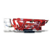
Verify that the maximum slope to stabi-
lize not exceed 27° (51%).
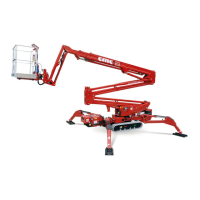
The lowering of the outriggers leads first to the con-
tact of the four outriggers plate with the ground and
then to the lifting of the frame.
Check the levelling of the machine at the bubble
level (Picture 16): the maximum inclination of the
frame allowed is equal to 1° (one degree).
When the stabilization ends, you can see the
switching on of the consent light for the aerial part 7
(Picture 4) on the ignition case.
4.4.2.1 Automatic stabilization with radio
control
If you want to stabilize the machine in automatic
mode, you can use the radio control:
• use the lever 11 (Picture 8): it causes the
simultaneous descent of the four outriggers
until the system reads the four limit switches
for the ground contact and the lifting of the
tracks;
• make sure that the consent indicator for the
use of the aerial part 7 (Picture 4) is on.
During stabilization phase, pressing the parking but-
ton P (Picture 8), together the stabilization lever,
you can raise all the machine without waiting the
predefined cycle of automatic stabilization.