MAN.241 Rev.5 ENG - Use and maintenance manual S23 page 43 of 127
In case there are not such conditions, it is
strictly forbidden to use the MEWP.
4. place the MEWP on the chosen area, using
travel buttons on radio control (par. 4.3.2.1);
5. define the work area with appropriate sig-
nals (white-red ribbon, white-red chains,
cones, etc.).
4.4.2 MEWP stabilization
The MEWP has different stabilization areas, accord-
ing to the different combinations of possible stabilizer
openings. Each of four outriggers can be positioned
in two different configurations (in addition to the clos-
ing one), corresponding to the following stabilization
areas (see par. 1.1).
a. narrow (4 feet closed);
b. wide (4 feet opened),
c. mixed (2 feet closed, and 2 feet opened).
A double electronic locking system uniquely ensures
the chosen working configuration.
The movement of the outriggers must be
possible only when the booms are resting
on their supports. This condition causes the
light up of the stabilization consent light 8
(Picture 4) on the ground control station.
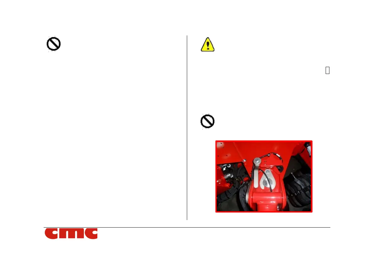
6. Lift the 4 pins which block the outriggers po-
sition (Picture 18). If this operation results
difficulty, move the stabilizer trying to rotate
it in the horizontal plane during the lifting.
It is forbidden, and unnecessary, to com-
pletely remove the pins from their seat.
Picture 18: outrigger pins.