To install the EXPLORER 8000 series
98-145510-E Chapter 3: Installation 3-7
12.Use LAN1 to access the web interface.
13.For LAN2, LAN3 and LAN4, see To configure the LAN network on page 6-14.
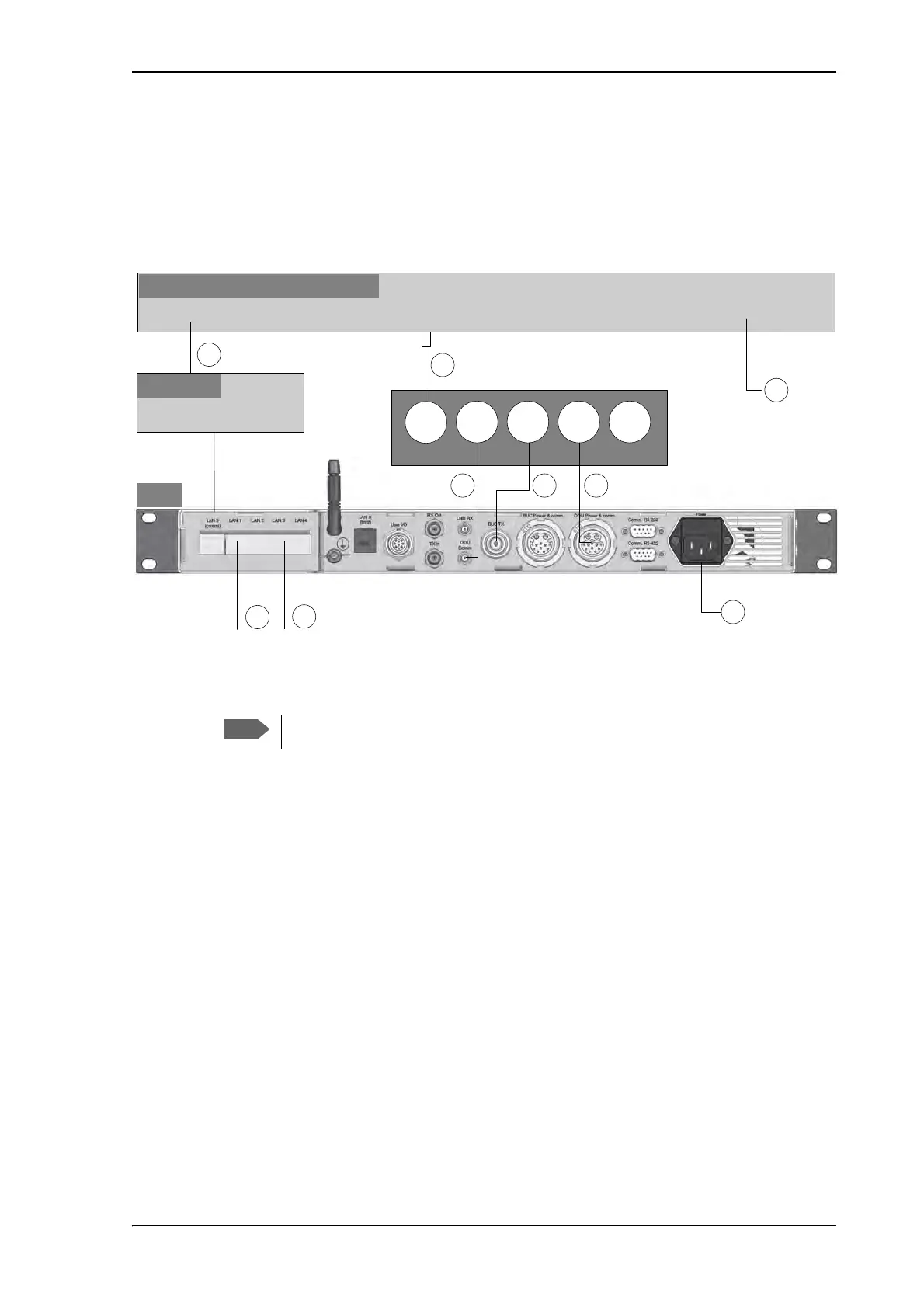
14.Connect ODU Comm. on the antenna pedestal to ODU Comm. on the ACU
Ka-band, connections
Connect the cables as described below:
1. Connect the LAN port on the VSAT modem to a router connected to the LAN 5 control
port on the ACU.
2. Connect the RX/TX RF connector on the VSAT modem to the LNB RX connector on
the antenna pedestal, using the F-to-SMA adapter included in the delivery (31-207170-
000). Seal the connection at the pedestal with splicing tape.
3. Connect the ODU Comm. connector on the antenna pedestal to the ODU Comm.
connector on the ACU. Seal the connection at the pedestal with splicing tape.
4. Connect the BUC TX connector on the antenna pedestal to the BUC TX connector on
the ACU (this connection is not used for the Ka-Band version, but is part of the cable
bundle). Seal the connection at the pedestal with splicing tape.
5. Connect the ODU Power & comm. connector on the antenna pedestal to the ODU
Power & comm. connector on the ACU.
6. Connect the ACU to an AC power source (Standard IEC320 on ACU).
7. Connect the VSAT modem to a suitable power source.
8. Use LAN1 to access the web interface.
9. For LAN2, LAN3 and LAN4, see To configure the LAN network on page 6-14.
Figure 4: Ka-Band: Connection between antenna, ACU and VSAT modem
9LDVDW6XUIEHDP,,PRGHP
$&8
$QWHQQDSHGHVWDOEXONKHDG
2'8
&RPP
%8&
7[
2'8
3RZHU
FRPP
%8&
3RZHU
FRPP
/$1
6HUYLFHSRUW
/$1
5;7;5)
3RZHULQSXW
/1%
5[
5RXWHU
/$1«/$1
)WR60$
DGDSWHU
/$1
The cables 2, 3, 4 and 5 are delivered as a cable harness.