Interfaces of the Antenna Control Unit (ACU)
98-145510-E Chapter 4: Interfaces 4-4
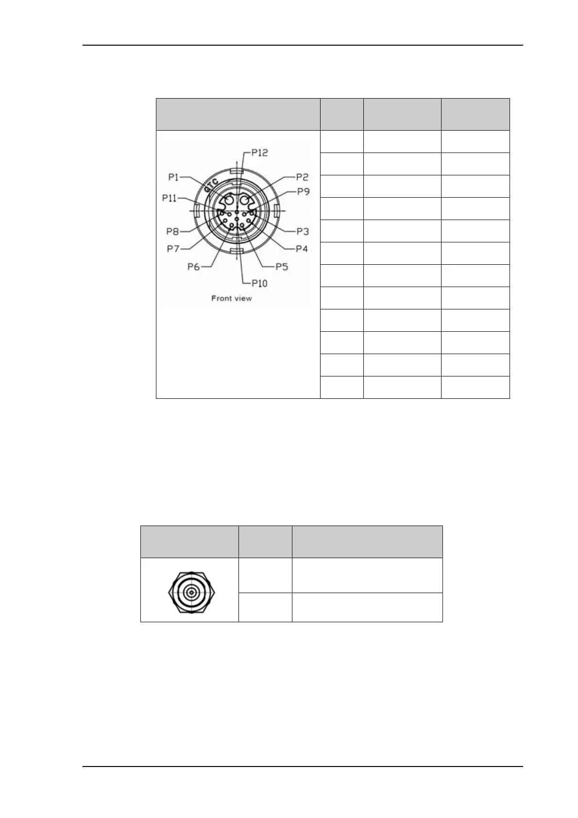
• BUC Power & Comm.: GTC C4 female connector.
• ODU Comm: SMA connector used for Housekeeping communication between the ACU
and the antenna.
4.1.6 Rx/Tx connectors for VSAT modem
RX Out and TX In are F-connectors for connection to the Rx and Tx channels of the VSAT
modem.
For step-by-step guidelines how to set up the VSAT modem see VSAT modem settings on
page C-1.
Outline
(on the ACU)
Pin Pin function Wire color
P1 BUC Power Black/Red
P2 BUC Power Rtn Black/White
P3 GND
P4 GND
P5 BUC Serial RX- Red
P6 BUC Serial RX+ Orange
P7 BUC Serial TX- Yellow
P8 BUC Serial TX+ Green
P9 Keyline - Blue
P10 Band Select + gray
P11 Keyline + Purple
P12 Band Select - White
Table 4-5: ACU Circular connector, BUC Power & comm, outline and pin assignment
Outline
(on the ACU)
Pin
number
Pin function
1 Inner conductor:
10 MHz clock, VSAT Rx/Tx
2 Outer conductor: GND (Shield)
Table 4-6: ACU F connector, Rx and Tx, outline and pin assignment