Interfaces of the Antenna Control Unit (ACU)
98-145510-E Chapter 4: Interfaces 4-3
4.1.5 Connectors for antenna connection
A cable bundle with all necessary cables between antenna and ACU is delivered with the
system. There are 5 connectors on the ACU for connection to the antenna:
• BUC TX: N-connector for signal and power to the BUC.
• LNB RX: SMA-connector for signal from the LNB to the ACU and power to the LNB
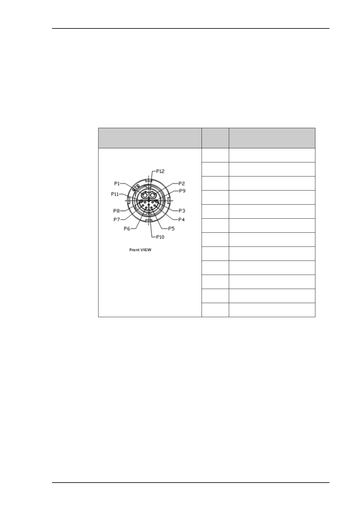
• ODU Power & comm: GTC C4 female connector for antenna power (ODU power),
stow indicator signal and internal system communication.
Outline
(on the ACU)
Pin Pin function
P1 ODU Power RTN
P2 ODU Power +48V
P3 Reserved
P4 Reserved
P5 GND
P6 Com1 antenna ID
P7 Com2 antenna ID
P8 Reserved
P9 Reserved
P10 Reserved
P11 GND
P12 Stow indicator switch
Table 4-4: ACU Circular connector, ODU Power & comm, outline and pin assignment