Interfaces of the Antenna Control Unit (ACU)
98-145510-E Chapter 4: Interfaces 4-7
4.1.9 User I/O
The User I/O connector is an 8-pin circular connector for user inputs and outputs, such as
muting the antenna or signalling Rx lock.
A short cable with a mating connector is available from Cobham SATCOM (part number S-
37-146760).
Pinout and functions
For specifications, see Specifications for User I/O connector on page A-5.
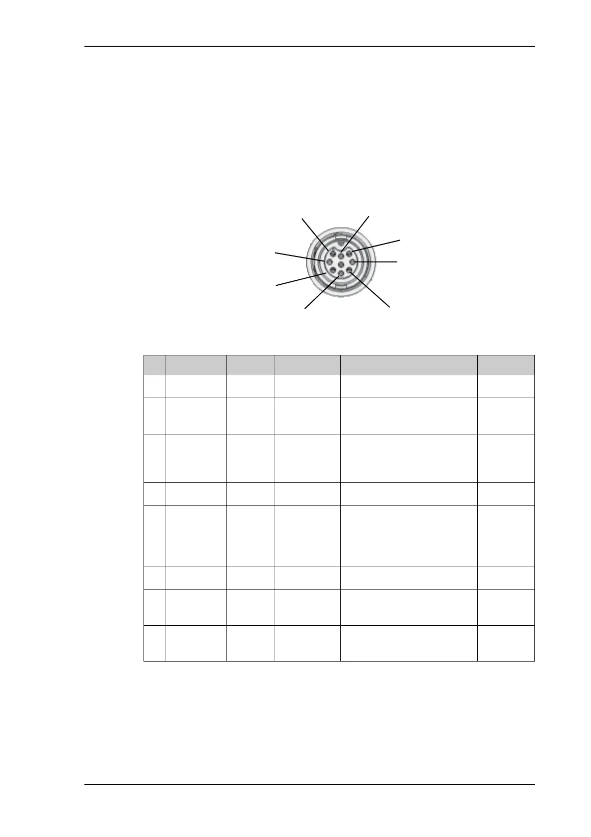
Figure 11: ACU User I/O connector, pinout
Pin Pin function Direction Type Description Wire color
a
a. The wire colors apply to the corresponding I/O cable available from Cobham SATCOM.
1 ACU Chassis common - - Black
2 RX Lock output 12 or 24 V
logic
High when RX locked Brown
3Stow
indicator
switch
output Switch in
antenna
Connected to GND (closed)
when antenna stowed,
otherwise open
Orange
4 TX Mute input 3-32 V logic Pull up to mute the antenna Yellow
5 Stow input input 3-32 V logic Float or pull up to force
antenna to stow. Ground to
allow standard control of
deploy/stow
b
b. The Stow input must be enabled in the web interface in order to work. See Stow input
(discrete I/O) on page 6-19.
Green
6 IF29 Aux1 input 3-32 V logic Spare input Blue
7 Do not
connect!
input or
output
3-32 V logic
or open drain
Spare input/output, for future
use
Violet
8 Do not
connect!
input or
output
3-32 V logic
or open drain
Spare input/output, for future
use
White
Table 4-12: ACU User I/O connector, Pin assignment, functions and wire color