2-18
Chapter 2: Installation
98-144591-D
DC Power cabling
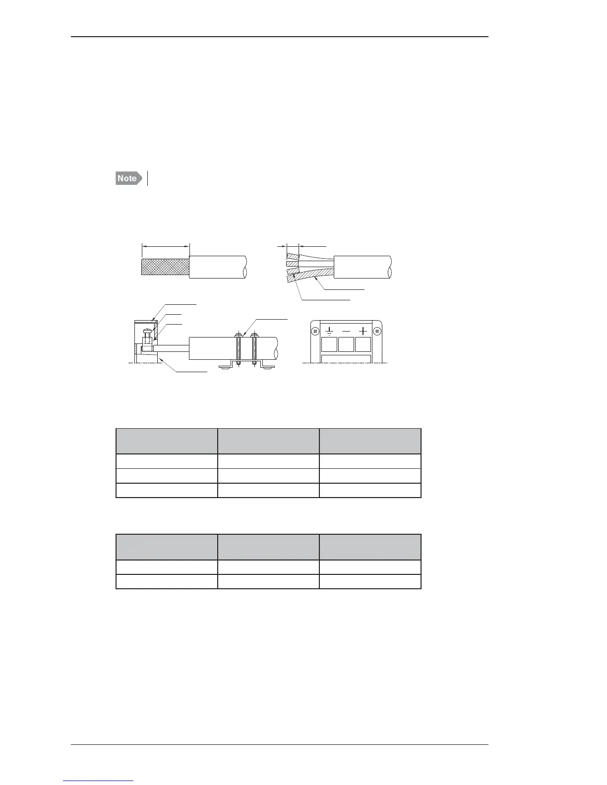
2.5 DC Power cabling
The supply leads are connected to the supply terminal of the Transceiver Unit. The supply terminal is
designed for 3 wire shielded power supply cable to meet international installation and EMC requirements.
The safety ground wire is connected to the terminal showing ground symbol and shielding connected
to the cable fi tting shown in page 2-3 must be well grounded to ships hull.
The earth connection of the equipment will not cause the battery to be earthed. Maximum permissible
peak voltage between the battery terminals and earth is 100 V.
Fusing must be provided in the supply leads for cable protection.
Cable lengths stated in tables are the total cable length from battery terminals via charger, shunt box,
DC distribution to TU DC-terminals.
Table below shows the necessary cable cross sections and external fuse ratings.
150 W/250 W
Max. cable length to
battery*
Recommended Cable
Sceened multiwire
External fuses
5 m 3 x 10 mm² (7 AWG) 40 A
8 m 3 x 16 mm² (5 AWG) 50 A
12 m 3 x 25 mm² (3 AWG) 63 A
500 W
Max. cable length to
battery*
Recommended cable
Sceened multiwire
External fuses
4 m 3 x 16 mm² (5 AWG) 100 A
6 m 3 x 25 mm² (3 AWG) 100 A

 Loading...