Chapter 3: Technical description3-2 98-144591-D
LEDs on the ECM boards can be used to verify the following items:
LED Normal state Status
FPGA A Off Transmit protection detected in current PTT ses-
sion (reset when PTT is released and pressed again)
FPGA D Off Reset from CPU has not been detected after FPGA boot.
FPGA B Blink Reserved
FPGA C Blink Reduced DAC clock
~
2.93Hz – not necessarily in
phase with FPGA LED
FPGA OWRFLW Off ADC Overfl ow
FPGA ALIVE Blink Alive led – Shall blink at
~
2.93Hz
LED C - On when transmitting – on while tuning – off in RX
LED B Off Lit if SWR protection is engaged
LED A - On when transmitting – off during tune – off in RX (TX monitor)
CPU HB Blink Kernel heartbeat
ARM CPU ALIVE Blink MFHF Application heartbeat
CPU Act Blink Off when CPU is idle
eMMC Act - Blinks when accessing fl ash fi le system
STATUS Blink DSP is running
ALIVE Off
3.5 PA and Filters module 60-122881
The PA and Filters module includes PA drivers, PA-stage, protection circuits, bias circuits, key circuit and
fi ve low-pass fi lters with relays and relay drivers. The PA and Filters receive the modulated RF input signal
from the RX/EX Signal Path and delivers the amplifi ed and fi ltered output signal to the TX/RX connector
via a receive/transmit relay on the Control/Intercon module.
The low-pass fi lters remove the unwanted harmonic frequencies from the PA signal. The Filpeak and
PAprotec outputs are monitoring signals for the Control/Intercon module. The driver and fi nal power
amplifi er stages are galvanically isolated on input and output as they are supplied directly from the 24
V DC input. The selection of low-pass fi lter is controlled by the Control/Intercon module.
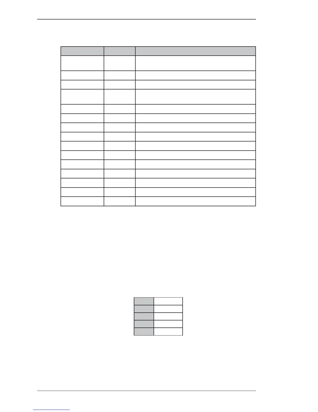
The PA fi lters cover the frequency ranges:
1.6 3.1 MHz
3.1 5.0 MHz
5.0 9.0 MHz
9.0 17.0 MHz
17.0 29.7 MHz
Technical description

 Loading...