2-13
Installation
Chapter 2: Installation
98-144591-D
Antennas
2.4 Antennas
With the SAILOR 6000B-series MF/HF a two-antenna confi guration is introduced which
implies that SSB, DSC and Telex reception all take place using a separate RX antenna, as
opposed to previous SAILOR MF/HF systems (SAILOR 6000A-, SAILOR 5000-, SAILOR
4000- and SAILOR 2000-series) in which SSB reception takes place using a common
TX/RX antenna.
The fact that SSB reception in the SAILOR 6000B-series takes place using a separate RX antenna implies
that the same considerations that were given to selecting the proper position of the combined RX/TX
antenna in previous systems, must be given to the position of both the RX and TX antenna in a SAILOR
6000B MF/HF system installation.
2.4.1 Transmitter Antenna
The transmitter antenna should be erected in the open, away from conducting object such as derricks
etc. which may cause reduction of the radiated power. Insulators used should be of the best type hav-
ing low leakage even when wet. Stays, wires, steel masts etc. should be either effectively grounded or
insulated. The antenna should also be
kept as far away as possible from elec-
trical equipment in order to minimize
noise. Electrical installations such as
cable braiding (screens) and instru-
ments in the vicinity of the antenna
should be grounded effectively, and
the instruments in question should be
fi tted
with noise-interference suppression
devices, effective in the range 0.1 MHz
to
30 MHz to avoid malfunction of these
instruments. The Antenna Tuning Unit
will tune on any frequency in the range
1.6 to 27 MHz to good whip and/or
wire installations of 12 to 18 m total
electrical length.
Shorter antennas, total electrical length
down to 8 m, can be used. Where pos-
sible longer antennas should be installed
to maximize the radiated power in the
lower frequency bands.
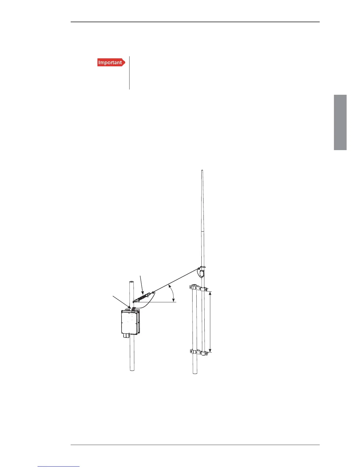
In general a recommended 12 m antenna
installation can be made up using an 8 m
whip and 4.5 m feeder or a 10 m whip
and 2.5 m feeder. In both cases the whip
should be mounted on a pole allowing for
the feeder to be erected at an angle of no
less than 45-60 degrees to create a ver-
tical antenna system. Using horizontal
feeders or feeders mounted at an angle
below 45 degrees usually transform the
antenna radiation resistance to a lower
value reducing the radiated power. The total antenna system should be kept well away from conductive
objects such as the mast, stays, wires etc. a horizontal distance of 6-8 m should be aimed at.
The antenna is terminated at the insulator at the top of the Antenna Tuning Unit. The insulator must be
relieved from mechanical stress by using max. 1 meter fl exible wire between the insulator and a support.
To maximize the radiated power and avoid fl ash over keep distance to metal parts as long as possible.
All wire junctions in the antenna system must be made with cable lugs of correct size according to the
wire gauge. This will prevent bad connections due to corrosion. For further corrosion proofi ng grease
may be applied to the cable joints.
(illustration refers to
the KUM803-1 antenna)
>45°
>1 meter
Insulator
Strain relieving insulator
Feed wire
ATU

 Loading...