2-14
Chapter 2: Installation
98-144591-D
Antennas
2.4.2 Considerations on antenna length requirements
Antenna impedance
The length of the transmitting antenna used with MF/HF equipment in general and the MF/HF equip-
ment specifi cally for purpose of this discussion is of utmost importance for the proper performance of
the equipment, i.e. the ability to tune properly to the antenna and the effective transmission range. In
terms of transmission range, more important than increasing the transmitter RF output power from say
150 W to 250 W is in fact the use of an adequate length antenna.
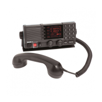
Comparatively, any practical length whip antenna remains too short for the wavelength for which it is
used, especially at the lower frequencies. For the frequency range 1.6 – 30 MHz defi ning the commercial
MF/HF marine band, the wavelength spans the range 190 – 10 m approximately.
A proper ground-plane for the TX antenna is essential in order for this to effectively radiate power
into the air. An RF transmitter connected directly to a whip antenna which is in the presence of the
ground-plane, looks into an impedance between the whip antenna and the ground-plane which varies
considerably with frequency and hence would cause varying load on the transmitter power amplifi er.
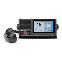
As an illustration of the typical impedance variation versus frequency of a whip antenna refer to below
fi gure.
1.6
3.2 6.4 12.8 25.6
Imp. (ohm)
Freq. (MHz)
1000
500
Typical impedance variation versus frequency for an 8m whip antenna with 4 m feed wire
Function of the Antenna Tuning Unit (ATU)
The MF/HF transmitter power amplifi er (PA) provides a fi xed output impedance of 50 ohms over its
operating frequency range to which the load (the antenna) should be matched (i.e. load should prefer-
ably be 50 ohms also) in order for the transmitter to deliver its full power output to the load. However,
with the varying impedance of an antenna, as described above such conditions will not be met . On the
remaining frequencies within the transmission band the varying mismatch between the transmitter
fi xed output impedance and the different impedance of the antenna at any given frequency, will result
in reduced RF power delivered to the antenna – in worst case hardly any power at all - if the antenna
was connected directly to the transmitter.
To overcome the frequency dependant mismatch between the transmitter output impedance and the
antenna (load) impedance, the ATU is put into the antenna circuit to provide variable compensation
counteracting the varying impedance of the antenna, the end result of which is the “transformation” of
this into a “fi xed” app. 50ohms load, as seen from the transmitter.
Ground-plane
Capacity C
Whip antenna

 Loading...