3-5
Technical description
Chapter 3: Technical description98-144591-D
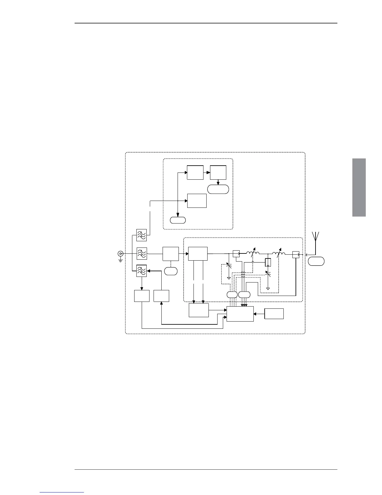
3.10.2 ATU module 60-131020 (500W)
The ATU module comprises of a tuning network, measuring system and micro-controller circuits. The
ATU module matches the impedance of the antenna to 50 ohm in order to gain the best possible SWR
towards the TU. The TU communicates tuning process and frequency information with the ATU. The
tuning network consists of capacitor bank 1, capacitor bank 2, and an inductor bank. With these banks it
is possible to form either an L-network or a pi-network. The capacitor banks and inductor bank are built
up by binary related capacitors and coils. The setting of capacitance and inductance is accomplished
by relays. To prevent overload of the relays, current detectors are incorporated in the inductor bank and
in capacitor bank 2 and information fed back to the transceiver unit to decrease the output power if
maximum permissible current is exceeded. To prevent overheating a temperature sensor is incorporated
which at excessive temperatures commands the transceiver to reduce the output power.
Block diagram
3.11 Power control and protection system
The Transceiver has an automatic power level system, which ensures that optimum power is delivered
to the Antenna. The Tune Sequence, which is automatically initiated when keying the transmitter after
a frequency change, makes the Tuning Network of the Antenna Tuning Unit tune to the best obtaina-
ble SWR. This is followed by an Automatic Level Control (ALC) adjustment according to the available
power supply voltage, measuring the output current of the PA Filters (FILPEAK @ 10 Vp at full output),
transmitting AM carrier, and setting the overall gain by the ALC voltage. It is now possible to transmit
at full output power unless protection is activated or LOW POWER is selected. The output power is
continuously monitored by the TU, and is automatically adjusted during transmission to provide reliable
communication.
Technical description

 Loading...