2-15
Installation
Chapter 2: Installation
98-144591-D
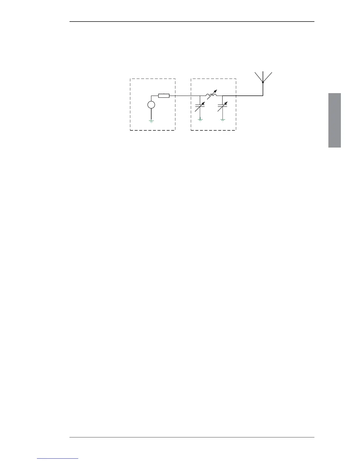
The required compensation is achieved through insertion of the correct combination of inductors
and capacitors in series with the antenna to form a resonance circuit at the given frequency. Hence,
depending on the impedance of the antenna (i.e. the transmission frequency) a suitable combination
of inductors and capacitors are put in-circuit through a number of relays, all controlled by the ATU
processor during the tuning process.
C1 C2
L
Rg = 50ohm
TX out
Antenna tuning
unit
Transmitter
Antenna
Schematic illustration of the insertion of ATU compensation circuitry
MF/HF ATU
The 6000-series ATUs will easily tune to the varying impedance of an 8 m whip antenna with a properly
installed 4 m feed wire, over the operating frequency range 0.15 – 30 MHz. A slightly shorter antenna
system might be used at the possible sacrifi ce of the ability to tune at the extreme low end of the
frequency band below 2 MHz.
However, the impedance of the antenna system is infl uenced by any nearby metallic objects such as
the vessel's superstructure and/or nearby metal poles/masts or stays/wires. Consequently, in order not
to alter the impedance of the antenna system which may eventually cause diffi culties for the ATU to
match the resulting impedance, the transmitting antenna should be kept at a distance of no less than
6-8 m from any such objects. Similarly goes for the feed wire connecting the ATU to the antenna which
should be kept at a minimum of 1 m from metallic objects.
It should be noted that even though the ATU will tune to the mentioned antenna system length, the
effective radiated power (i.e. the effi ciency of the antenna) in the low frequency end may suffer com-
pared to longer antenna systems of recommended electrical length 10-18 m.
Electrical connection of transmitting antennas
The connection to the transmitting antenna is by a single ended wire - the feed wire - connecting from
the ATU insulator (see fi gure on page 2-12). This feed wire adds to the electrical length of the antenna
(when correctly installed), thus in effect increasing the effi ciency of the antenna. The longer the feed wire
the better the effi ciency of the antenna system consisting of transmitting antenna and the feed wire.
For direct addition of feed wire length to antenna electrical length, the feed wire should be vertically
installed as an extension downwards of the transmitting antenna. In practice, where the ATU is placed
between the feed wire and the ground-plane (steel deck), the direct vertical installation of the feed wire
may be diffi cult in terms of total height. This may partly be accounted for by allowing the feed wire
installed at an angle of at least 45 degrees with the horizontal plane. Installing the feed wire at lower
angles will create capacitance to the ground-plane in turn decreasing the effi ciency of the antenna.
Antennas

 Loading...