2-12
Chapter 2: Installation
98-144591-D
In situations where the grounding connection of the ATU/antenna system cannot be kept within the
indicated length limit, fi nding workable alternative means of grounding through e.g. a longer grounding
connection between the ground-plane and the ATU, may require trial and error methods to be applied
in order to fi nd a workable solution. It is important here to keep in mind the initial statement of this
paragraph saying that the longer the grounding connection, the higher the RF impedance of this and
consequently the RF loss, resulting in less power radiated from the antenna.
It should also be noted that, as no two situations are alike, having found a workable solution for one
situation this may not necessarily prove workable for another.
2.3.6 Transceiver Unit and Control Unit
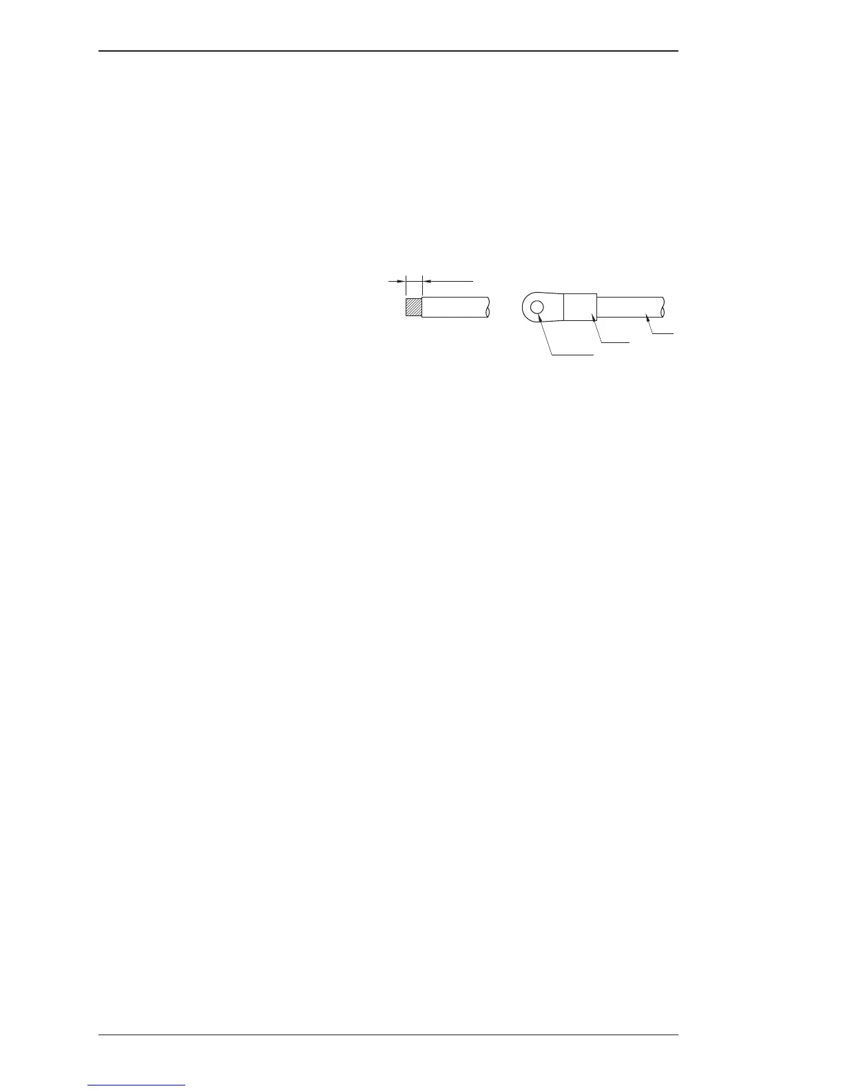
The Transceiver Unit is preferably grounded
separately to the ships metal in the shortest
possible way. A 10mm² (AWG 7) to 16mm²
(AWG 5) ground wire is connected to the
ground terminal (cable clamp) at the bot-
tom of the unit.
Grounding connections

 Loading...