2-11
Installation
Chapter 2: Installation
98-144591-D
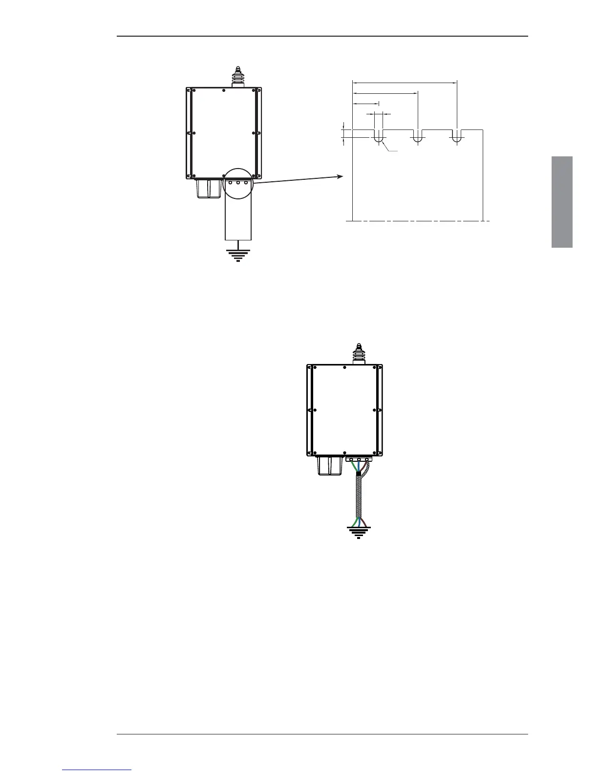
In case the described copper strap material should not be readily available, a corresponding length of
a 3-conductor cable of minimum 25mm² (AWG 3) stranded conductor cross sectional area may be
used as illustrated below. This illustration further shows how shielding of the grounding connection to
reduce RF radiation from the ground leads may be achieved, if required, by grounding the cable shield
at the ATU end only.
Shielded ground downlead
It is recommended to install the ATU by means of the ATU mounting bracket shown in section 2.2.4
as this stainless steel bracket can be welded to the super structure and will provide the best possible
none corroding ground connection.
On ships constructed of non-conductive material such as wood or fi berglass other means of establishing
a ground plane must be found, such as an external copper ground plate below the water line (e.g. a
standard Dynaplate) or utilizing existing internal steel framing or e.g. connecting all accessible metal
parts together and use this a ground-plane.
As stated in paragraph 2.3.4 it is important that ground loops be minimized by taking the ATU to the
ground rather than taking the ground to the ATU. However, it should not be attempted to install the
ATU indoors as this would result in a need to pass the antenna feed wiring through deck and/or bulkhead
feedthroughs etc. having severe impact on the RF performance, not to mention the RF fi elds generated
around the feed wiring causing problems in other installations and equipment.
Grounding connections

 Loading...