Adjustments
HF SSB Transceiver 9323/9360/9390/9780 Technical Service Manual 7-5
Test mode
The Test mode provides eleven test set-up procedures and 23 special channels.
They enable the service technician to check the transceiver’s performance and
when necessary, carry out minor adjustments to ensure the equipment meets the
specifications.
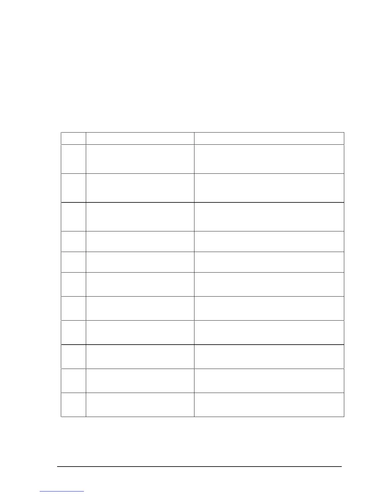
Table 7-4 details the eleven test facilities and the specific area targeted for the test.
Table 7-5 and Table 7-6 detail the test channels.
Table 7 -4: Test facilities
Test Details of Test Checks
1 Sets VCO1 to 60 MHz
Sets VCO2 to 44.5445 MHz
For checking VCO1 and VCO2 at centre
frequency, see page 7-10, VCO1 check and page
7-10, VCO2 check.
2 Sets VCO1 to 75 MHz
Sets VCO2 to 44.5485 MHz
For checking VCO1 and VCO2 at top frequency,
see page 7-10, VCO1 check and page 7-10, VCO2
check.
3 Sets VCO1 to 45.25 MHz
Sets VCO2 to 44.5405 MHz
For checking VCO1 and VCO2 at bottom
frequency, see page 7-10, VCO1 check and page
7-10, VCO2 check.
4 Programs VCO1 between two
frequencies centred at 8.4 MHz
Used for aligning the 45 MHz BPF with a CRO
and Signal Generator.
5 Programs VCO1 and VCO2 to
44.544 MHz
Used for aligning the 45 MHz BPF using a
spectrum analyser.
6 Sets Rx frequency to 1.40 MHz
*
Selects HPF 2–3.1
For aligning L19 in 2–3.1 HPF, see page 7-12,
HPF/LPF filter alignment.
7 Sets Rx frequency to 2.18 MHz
Selects HPF 3.1–4.8
For aligning L16 in 3.1–4.8 HPF, see page 7-12,
HPF/LPF filter alignment.
8 Sets Rx frequency to 3.48 MHz
Selects HPF 4.8–7.47
For aligning L13 in 4.8–7.47 HPF, see page 7-12,
HPF/LPF filter alignment.
9 Sets Rx frequency to 5.30 MHz
Selects HPF 7.47–11.6
For aligning L10 in 7.47–11.6 HPF, see page 7-12,
HPF/LPF filter alignment.
10 Sets Rx frequency to 8.26 MHz
Selects HPF 11.6–18
For aligning L7 in 11.6–18 HPF, see page 7-12,
HPF/LPF filter alignment.
11 Sets Rx frequency to 12.6 MHz
Selects HPF 18–30
For aligning L4 in 18–30 HPF, see page 7-12,
HPF/LPF filter alignment.
*
For 1.6 MHz Option LF fit 1.6 link on Rx/Exciter PCB after this test.