Adjustments
HF SSB Transceiver 9323/9360/9390/9780 Technical Service Manual 7-17
45 MHz filter alignment (08-05322)
108-05322
There are two methods of aligning the 45 MHz BPF located on the 08-05322
Rx/Exciter PCB. The two methods are:
• using an oscilloscope, a signal generator and a simple jig
• using a spectrum analyser with a tracking generator
These methods are detailed in the following two sections.
Alignment—method 1
The following steps details the alignment procedure using an oscilloscope, a
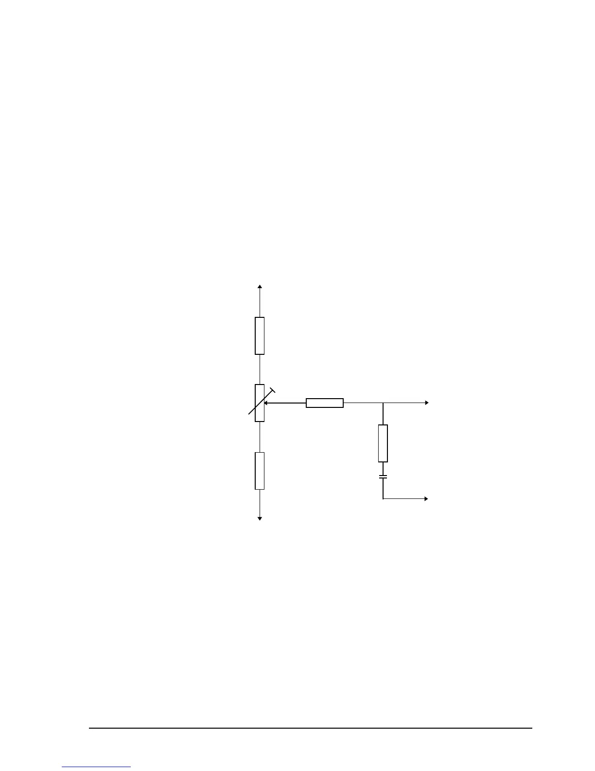
signal generator and a simple jig. The circuit for the test jig is shown in
Figure 7-3.
To
F
Figure 7 -3: Circuit for test jig
q Connect the test jig to the Rx/Exciter PCB [108-05322] as shown in
Figure 7-3.
q Unsolder sweep link S adjacent to TP1.
This opens the synthesiser control loop by disconnecting the DC control line
to the varicaps D20-D23.
q Remove the shorting link parked on the two ground pins E-E and fit to B-E
of noise limiter TP202.