Adjustments
HF SSB Transceiver 9323/9360/9390/9780 Technical Service Manual 7-15
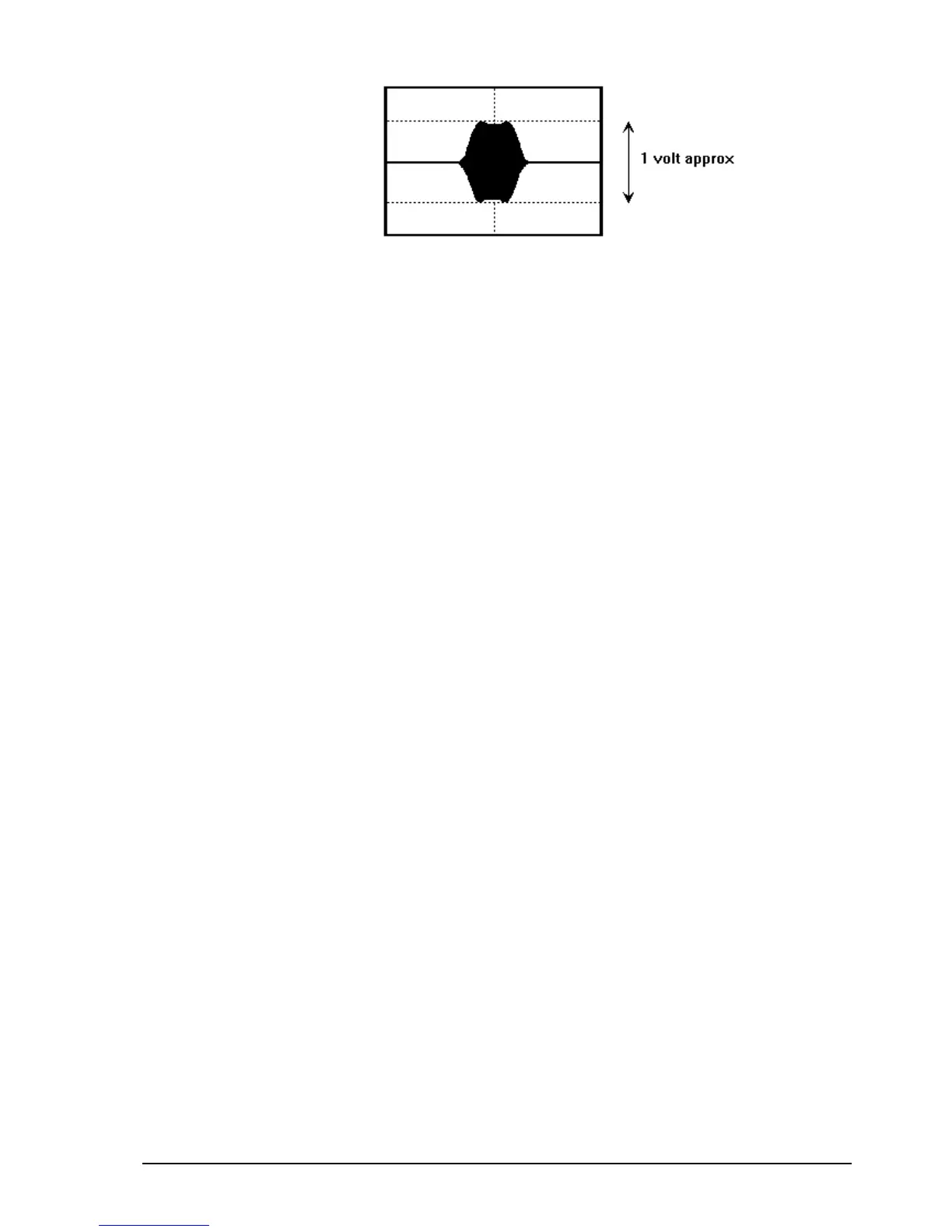
Figure 7 -2: Ripple response
q Remove the shorting link to B–E and return it to its parking position (ground
pins of link E–E).
q Solder sweep link S.
Alignment—method 2
The following steps detail the alignment procedure using a spectrum analyser and
tracking generator in Test mode.
q Select Test 5.
q Remove the shorting link parked on the two ground pins of link E–E and fit
the link to B–E of noise limiter TP202.
Fitting the shorting link to B–E opens the noise limiter gate.
q Connect the tracking generator set to an output of 7 mV RMS (–30 dBm)
direct to the receiver input.
q Connect the spectrum analyser input to TP201 (50 Ω input is permitted). Set
up the spectrum analyser as follows:
Centre frequency
455 kHz
Frequency span
100 kHz (10 kHz per division)
Vertical level
10 dB per division
q Adjust the spectrum analyser sensitivity to about −50 dBm to display the
frequency response of the 45 MHz BPF.
q Adjust transformers T3 and T4 and inductor L30 for less than 2 dB ripple
over 15 kHz span centred at 455 kHz. If desired, the vertical level can be
changed to 2 dB per division to improve the resolution.