General information
2-10 HF SSB Transceiver 9323/9360/9390/9780 Technical Service Manual
Connectors
The following tables detail the pin connections and functions of the front and rear
connectors. Details are also provided for the cables used for channel and cloning
programming.
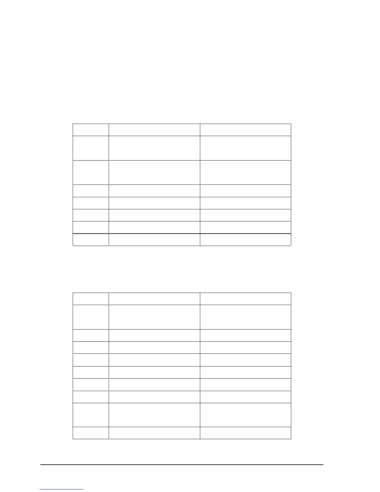
Microphone
Table 2 -1: Microphone connector (J3) pin function
Pin No. Function Signal Levels
1 Speaker Audio Output 12 V PP (max)
4 Ω (min)
2 Microphone Input 50 mV PP
12 kΩ I/P impedance
3 PTT Ground 0 V
4 Data In 0–5 V logic
5 PTT Active & Data Out Active low, 0–12 V logic
6 "A" Rail 13.6 V nominal
7 To Front Panel Speaker
Remote control
Table 2 -2: Remote Control connector (P204) pin function
Pin No. Function Signal Levels
1 Speaker 12 V PP
4 Ω min impedance
2 Remote PTT 5 V logic, Active low
3 EXT A/F I/P Future use
4 Power On
Momentary 0 V = PWR On
5 Data I
2
C5 V logic
6 No Connection
7Clock I
2
C5 V logic
8 "S" & RF 4.5 to 0.25 V Rx
0 to 4.25 V Tx
9 0 V Ground