Code Blue
•
259 Hedcor Street
•
Holland, MI 49423 USA
•
800.205.7186
•
www.codeblue.com
GU-137-Hpage 13 of 67
IP1500 and IP2500 Series
Administrator Guide
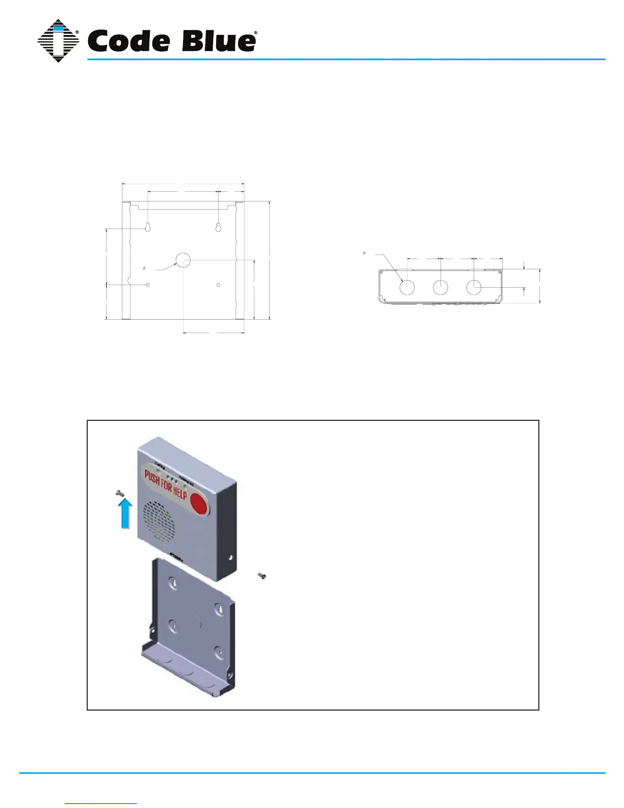
5.3 Surface Mount IP2500 Series
IP2500SeriesSurfaceMount:7.25”wx7.25”hx2.00”d
7.41
7.17
3.59
3.70
1.56 4.28
2.09
3.39
.88
KNOCK OUT
1.70 2.00 2.00
1.10
.88
KNOCK OUT
2.03
7.41
7.17
3.59
3.70
1.56 4.28
2.09
3.39
.88
KNOCK OUT
1.70 2.00 2.00
1.10
.88
KNOCK OUT
2.03
BackView
• First,removethetworetainingscrews,onefrom
each side of the case
• Removetherearmountingplatebyslidingit
downward
• Usethemountingplateasyourguideonthe
wall,markthemountingandconduitholes
• Removetherearmountingplateandcreatethe
requiredholes,attachthemountingplatetothe
wall
• Pull CAT 5e cable through the conduit hole in
therearmountingplate
• ConnectCAT5ecabletotheEthernetporton
the PCB
• SlidetheIP2500Seriescasedown,starting
fromthetopoftherearmountingplate
• Replacethetworetainingscrews
BottomView
Vertical
Orientation
NOTE:Bydesign,nomaingasketisneededtosealtheenclosures.Theinstallerisresponsiblefor
sealingallscrewswiththreadseal,aswellasapplyingtheproperconduitforaweather-tightseal.