RECHARGING THE BATTERIES
The batteries must be charged prior to the rst use, and when they don't provide enough power for tasks that could formerly be performed without diculty.
ATTENTION: to avoid any permanent damage to the batteries, it is essential to avoid their complete discharge; begin recharging them within a few minutes of noting the “discharged batteries” signal.
ATTENTION: never leave the batteries completely run down, even if the machine is not being used.
To recharge the batteries, proceed as follows:
1. Bring the machine to the battery recharging area.
N.B.: park the machine in an enclosed place, on a at and level surface; near the machine there must be no objects that could either damage it, or be damaged through contact with it.
WARNING: the battery recharging area must comply with the requisites of Standard CEI EN 50272-3, or those currently in force in the country of use.
2. Check that the recovery tank is empty, otherwise read paragraph “EMPTYING THE RECOVERY TANK”.
3. Sit on the driver’s seat.
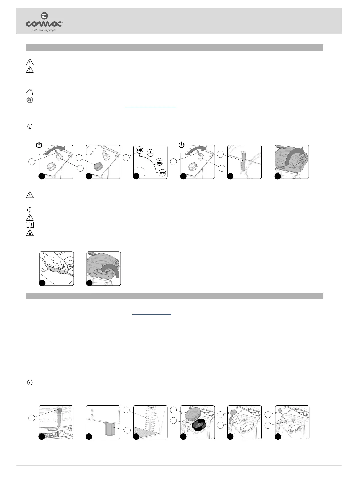
4. Insert the key (1) into the main switch (2) on the control panel. Bring the main switch (2) to position “I” by turning the key a quarter turn clockwise (Fig. 1).
5. Use the i-drive command knob (3) (Fig. 2) to select the “transfer” program (A) (Fig. 3).
N.B.: in this way, both the brush head body and the squeegee body will move to their idle position.
6. Bring the main switch to its “0” position by turning the key (1) a quarter turn anti-clockwise (Fig. 4). Remove the key from the main switch.
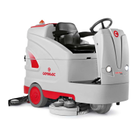
7. Unhook the tank rotation latch (4) (Fig. 5) and turn the recovery tank into the maintenance position (Fig. 6).
8. Disconnect the battery connector from the machine's main system connector (Fig. 7).
ATTENTION: the following operations must be carried out by qualied personnel. An incorrect connection of the connector may cause problems with machine functioning.
9. Connect the external battery charger cable to the battery connector.
N.B.: the coupling connector of the battery charger is consigned inside the bag containing this instruction booklet, and must be assembled on the cables of the battery charger as indicated in the instructions.
CAUTION: before connecting the batteries to the battery charger, make sure it is suitable for the batteries used.
CAUTION: carefully read the Use and Maintenance Manual of the battery charger used for recharging.
CAUTION: keep the battery inspection carter open for the duration of the battery recharging cycle to allow gas fumes to escape.
10. When the recharge cycle is complete, disconnect the external battery charger cable from the battery connector.
11. Connect the battery connector to the machine's main system connector.
12. Rotate the recovery tank into the working position (Fig. 8). Block the rotation with the latch (4) (Fig. 5).
1 4 5 62 3
1 1
2 2
4
3 A
ON OFF
7 8
FILLING THE SOLUTION TANK WITH WATER
Before lling the solution tank, carry out the following steps:
1. Take the machine to the usual place for lling the solution tank.
2. Perform the procedure for securing the machine (see the section titled “SECURING THE MACHINE”).
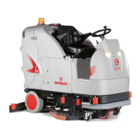
3. Check to make sure that the solution tank drainage cap (1) is closed. If this is not the case, close it (Fig. 1).
4. Check to make sure that the water system's lter cap (2), located on the front left-hand side of the machine, is closed, and close it if necessary (Fig. 2).
5. Fill with clean water, at a temperature no higher than 50°C (122°F) and no lower than 10°C (50°F).
6. Check the water level through the tube (3) located under the operator's seat (Fig. 3).
The tank can be lled with water in the following ways:
A) lling through the side inlet:
• Remove the cap (4) on the side of the machine (Fig. 4), ll the solution tank using a hose or a bucket.
• Before lling the tank, check that the lter (5) is correctly positioned above the inlet (Fig. 4).
B) lling through the quick lling pipe:
• Remove the ller pipe (6) from its housing (Fig. 5), remove the closure cap (7) and insert inside the water ller pipe.
• Remember to remove the cap (4) so the air can be properly vented.
N.B.: the ller pipe (6) supports the water ller pipe.
C) lling through the optional quick lling kit:
• Remove the cap (8) positioned above the quick coupling (9) (Fig. 6), insert the water ller pipe into the quick coupling.
• Remember to remove the cap (4) so the air can be properly vented.
1 5 62 3 4
1
7 9
6 8
2
3 4
5
16