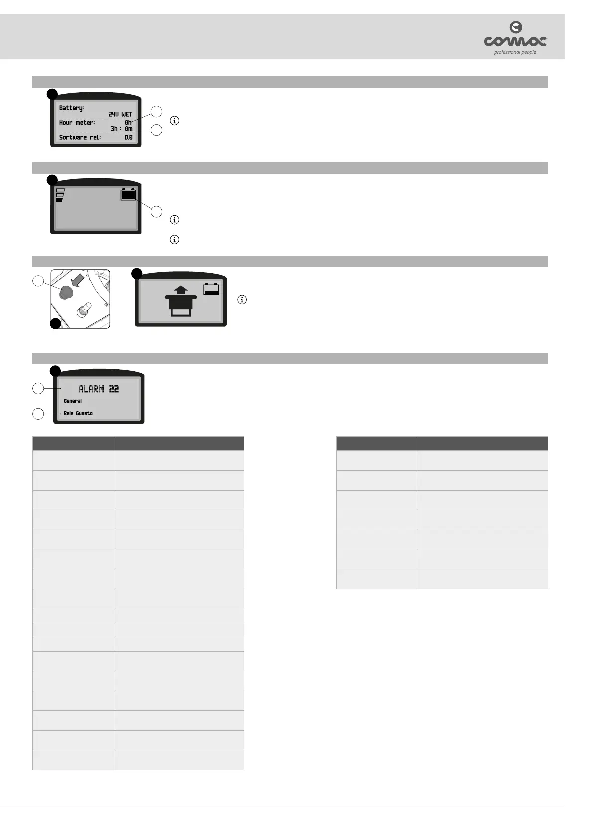
HOUR METER
Through the control display, in the screen after switching on, it is possible to view the hours of work performed by the machine in the central part of the
screen (Fig. 15).
In the rst line indicates the total use time of the machine (12) and the second line indicates the partial use time of the machine (13).
N.B.: The numbers followed by the letter “h” identify the hours, while the numbers followed by the letter “m” identify the tenths of an hour (a tenth of
an hour corresponds to six minutes).
15
12
13
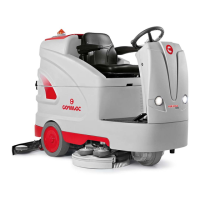
BATTERY CHARGE LEVEL INDICATOR
The machine's control panel contains the control display. At the top right of the work screen, there is a graphic symbol (14) representing the battery charge
level indicator (Fig. 16).
The indicator is composed of 5 charge levels, each of which represents about 20% of residual charge. With a residual charge of 20% the graphic symbol
starts to ash and after a few second it will appear in larger dimensions in the middle of the screen, under these conditions take the machine to the usual
place to charge the batteries.
N.B.: A few seconds after the battery charge level reaches 20%, the brush motors switch o automatically. With the remaining charge it is possible
to complete the drying process before starting the recharge.
N.B.: A few seconds after the battery charge level reaches 10%, the vacuum motor switches o automatically. With the remaining charge, it is still
possible, however, to move the machine to the location designated for its recharging.
16
14
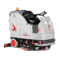
EMERGENCY BUTTON
if there are any problems while you are working, press the emergency button (15) on the control panel (Fig. 17). This function
interrupts all functions active at that moment, in this way both the brush head body and the squeegee body will rise from the
oor and automatically switch o with the expected delays.
N.B.: As soon as the emergency button (15) is pressed, the dedicated symbol appears on the control display (Fig. 18).
Once you have stopped the machine and solved the problem, to resume work proceed as follows:
1. Turn the main machine switch to “0”, turn the key a quarter turn anti-clockwise.
2. Move the emergency switch (15) to the resting position, turn the switch one forth of a turn to the right (as indicated by the
arrows engraved in it).
3. Turn the main machine switch to “I”, turn the key a quarter turn clockwise.
17
18
15
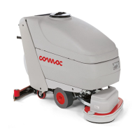
ALARM SCREEN
When an error occurs, the corresponding alarm screen (Fig. 19) will appear on the control display.
The display of the alarm consists of a rst ashing line relating to the code (16) and the source of the error (17) (Fig. 19), while in the second line displays a
summary (18) of the error description.
19
16
17
ALARM #id MEANING
AL_1: Function
Brushes Overcurrent.
Brushes overload protection
AL_2: Function
Vacuum cleaner overcurrent
Vacuum cleaner amperometric protection
AL_3: Function
Power Board Damaged
Damaged power stage
AL_4: Function
Overcurrent
Overcurrent on brush or vacuum cleaner outputs
AL_5: Function
Overtemperature
Thermal cut-out protection on the brushes -
vacuum cleaner stage
AL_8: Function
Act1: time-out
Brushes actuator: nal position not reached
AL_9: Function
Act2: time-out
Squeegee actuator: nal position not reached
AL_12: Traction
Generic AL.
Undervoltage
Overvoltage
Key o
EEprom alarm
AL_13: Traction
Pedal Faulty
Pedal jerking
AL_14: Traction
Pedal Pressed
Pedal pressed at startup
AL_15: Traction
Overtemperature
Thermal cut-out protection on traction stage
AL_16: Traction
Power Board Damaged
Traction power stage damaged
AL_17: Traction
Overcurrent
Overcurrent on Traction output
AL_18: Traction
Amperometric protection
Traction amperometric protection
ALARM #id MEANING
AL_19: Traction
PW stage relay
Traction - Fuse power stage damaged
AL_20: General
Memory Error
Error reading internal memory
AL_21: General
Issue with Key
Key sequence incorrect
AL_22: General
Relay Faulty
General relay damaged
AL_23: General
Overvoltage
Overvoltage
AL_25: General
Button conn.
No dashboard-function communication
AL_26: General
RX-TX Traction
No traction-function communication
21