SERVICE BRAKE
The machine is equipped with an electronic braking system (positioned in the front traction hub) and a mechanical drum brake
system (positioned on the rear wheels).
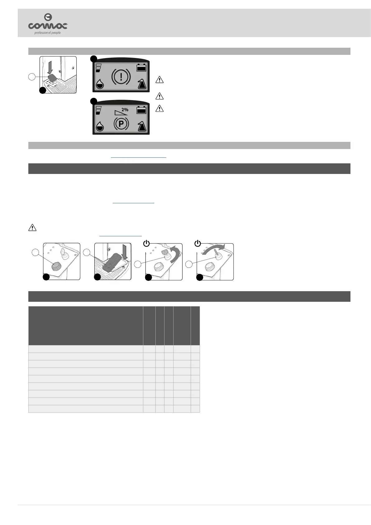
To brake, in normal conditions, just remove your foot from the accelerator pedal. In case of malfunction of the electronic
braking system or if necessary, operate the pedal (18) located on the front left of the machine (Fig. 20).
ATTENTION: If when working, the symbol shown in (Fig. 21) appears in the control display, this means that the service
brake is active for more than ve seconds. With the machine fully stopped, check that the service brake pedal has
returned to its rest position.
ATTENTION: If when working, the symbol shown in (Fig. 21) is ashing in the control display, this means that the brake
uid level is low.
CAUTION: If during the check when the machine is turned on there is a problem with the electro-brake, the acoustic
signal will sound continuously for ten seconds during which the symbols will ash alternately on the control display
shown in the image (Fig. 22). To solve the problem, contact an authorised technical assistance centre. With the alarm
active, the machine can not work on surfaces with an inclination greater than 2%.
20
21
22
18
OVERFLOW DEVICE
The machine is equipped with a mechanical device (oat) under the recovery tank lid that, when the recovery tank is full, shuts o the air to the vacuum motor intake to protect it; the sound of the vacuum motor
will then be deeper. To empty the recovery tank (read “EMPTYING THE RECOVERY TANK”).
AT THE END OF THE WORK
At the end of the work, and before carrying out any type of maintenance, perform the following operations:
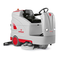
1. Select the TRANSFER mode using the knob (1) (Fig. 1) on the control panel.
2. Press the drive pedal (2) (Fig. 2) to begin moving the machine.
3. Take the machine to the maintenance area.
4. Switch o the machine turning the key (3) of the main switch a quarter turn anti-clockwise (Fig. 3). Remove the key from the instrument panel.
5. Carry out all the procedures listed in the paragraph “ROUTINE MAINTENANCE” indicated in the column “AT THE END OF THE WORK”.
6. Sit on the driver’s seat.
7. Insert the key (3) into the main switch on the control panel. Set the main switch to “I” (Fig. 4).
8. Press the drive pedal (1) (Fig. 1) to begin moving the machine.
9. Take the machine to the designated machine storage place.
ATTENTION: Park the machine in an enclosed place, on a at surface; near the machine there must be no objects that could either damage it, or be damaged through contact with it.
10. Secure the machine, see the section titled “SECURING THE MACHINE”.
3 4
3 3
OFF ON
1 2
1 2
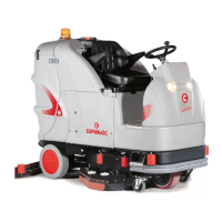
ROUTINE MAINTENANCE
TYPE OF MAINTENANCE
AT THE END OF
THE WORK
DAILY
WEEKLY
BEFORE A
LONG PERIOD
OF NON-USE
TRANSPORT
EMPTYING THE RECOVERY TANK X X X
CLEANING THE SQUEEGEE BODY X X X
CLEANING THE RECOVERY TANK FILTER-FLOAT X X
CLEANING THE BRUSH HEAD BRUSHES (SCRUBBING VERSION) X X
CLEANING THE RECOVERY TANK X X
EMPTYING THE SOLUTION TANK X X X
CLEANING THE WATER SYSTEM FILTER X X
CLEANING THE VACUUM TUBE X X
CLEANING THE DETERGENT TANK (CDS VERSIONS) X
22