CLEANING THE RECOVERY TANK
To clean the recovery tank, proceed as follows:
1. Take the machine to the maintenance area.
NOTE: the place designated for this operation must comply with current environmental protection regulations.
2. Make sure the machine has been secured (see the section titled “SECURING THE MACHINE”).
CAUTION: users are advised to always wear protective gloves, to avoid the risk of serious injury to hands.
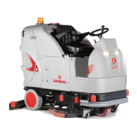
3. Release the recovery tank drainage tube (1), at the back of the machine, from the retainers (Fig. 1), unscrew the cap and place it on the ground.
4. Grip the handle (2) on the back of the recovery tank cover and remove it (Fig. 2).
5. Rinse the inside with a jet of water, if necessary use a spatula to remove the sludge that has accumulated at the bottom of the tank.
6. Repeat the operations in reverse order to reassemble all the parts.
NOTE: the place designated for this operation must comply with current environmental protection regulations.
2
2
1
1
CLEANING THE BRUSH HEAD BODY BRUSHES
Careful cleaning of the brush guarantees better cleaning of the oor as well as a longer brush head gearmotor lifespan. To clean the brush, proceed as follows:
1. Take the machine to the designated maintenance place.
NOTE: the place designated for this operation must comply with current environmental protection regulations.
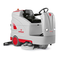
2. Select the “TRANSFER” function using the knob (1) (Fig. 1).
3. When the button (2) on the control panel (Fig. 2) is pressed for the rst time, the conrmation request symbol (Fig. 3) will appear in the control display.
4. Pressing the button (2) again will activate the brush release function.
N.B.: Once the release sequence has been activated, it is not possible to activate other functions or move the machine.
CAUTION: During this operation, check there are no people or objects near the brush.
5. Clean the brush under a stream of running water to remove any impurities from its bristles. Check the wear status of the bristles and replace the brushes if they are excessively consumed (the bristles' protrusion
must not be less than 10 mm; this distance is indicated on the brush by the yellow band). In order to replace the brushes, see the section titled “INSTALLING THE BRUSH HEAD BRUSHES”.
N.B.: you are advised to invert the right and left-hand brushes every day.
ATTENTION: If the brushes are not new however, and have deformed bristles, it is better to reassemble them in the same position (the right-hand one on the right, and the left-hand one on the left),
to prevent the dierent inclination of the bristles producing an overload on the brush motor as well as excessive vibrations.
2
3
2
1
1
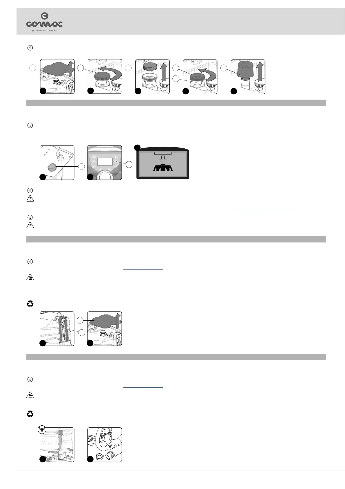
N.B.: If the polyurethane ring on the oat body (Fig. 5) is excessively worn or damage contact the nearest service centre.
8. Repeat the operations in reverse order to reassemble all the parts and move on the second oat lter.
3 4 5
1 2
1 2 3 4
5
6
EMPTYING THE SOLUTION TANK
Proceed as follows to empty the solution tank:
1. Take the machine to the maintenance area.
NOTE: the place designated for this operation must comply with current environmental protection regulations.
2. Make sure the machine has been secured (see the section titled “SECURING THE MACHINE”).
CAUTION: users are advised to always wear protective gloves, to avoid the risk of serious injury to hands.
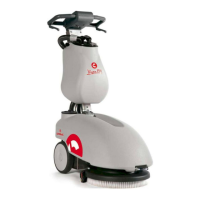
3. Remove the drainage hose of the solution tank from the clamps; it is located at the rear of the machine (Fig. 1).
4. Bend the end of the drainage tube in order to create a choke and prevent the content from coming out (Fig. 2), then position the tube on the discharge surface, unscrew the cap, and gradually release the tube.
NOTE: the place designated for this operation must comply with current environmental protection regulations.
5. Repeat the operations in reverse order to reassemble all the parts.
21
24