COMBAT
®
CTU UNIT HEATERS INSTALLATION OPERATION AND SER VICE MANUAL
8 of 46
SECTION 5: SPECIFICATIONS
5.1 CTUA
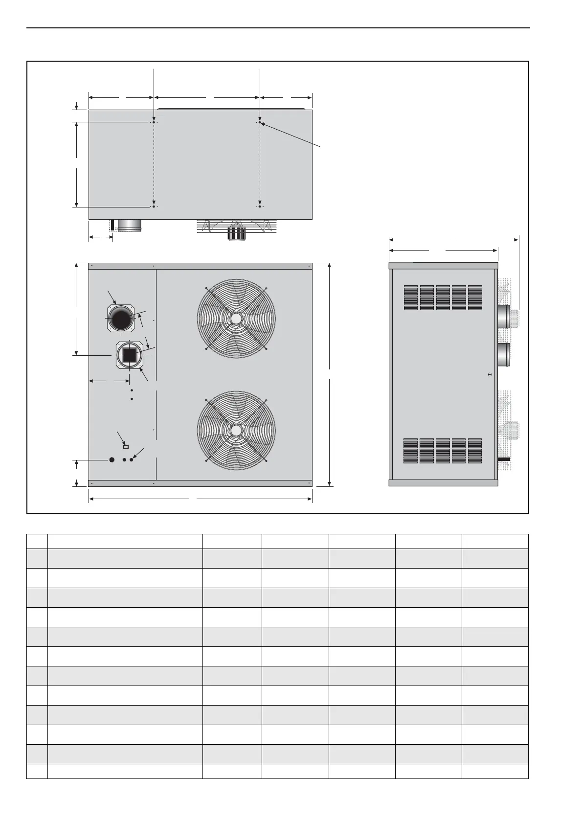
Dimension Data - CTUA (All Models)
Model 75 90 100 115
A
Width
mm
(in)
1327
(52.3)
1327
(52.3)
1327
(52.3)
1327
(52.3)
B
Height
mm
(in)
1100
(43.3)
1100
(43.3)
1345
(53)
1345
(53)
C
Support Spacing
mm
(in)
627
(24.7)
627
(24.7)
627
(24.7)
627
(24.7)
D
Support Spacing
mm
(in)
312
(12.3)
312
(12.3)
312
(12.3)
312
(12.3)
E
Support Spacing
mm
(in)
388
(15.3)
388
(15.3)
388
(15.3)
388
(15.3)
F
Centre of Flue
mm
(in)
346
(13.6)
346
(13.6)
537
(21.1)
537
(21.1)
G
Centre of Flue/Air Intake
mm
(in)
225
(8.9)
225
(8.9)
225
(8.9)
225
(8.9)
H
Position of Flue
mm
(in)
260
(10.2)
260
(10.2)
260
(10.2)
260
(10.2)
J
Gas Inlet Position
mm
(in)
220
(8.7)
220
(8.7)
220
(8.7)
220
(8.7)
Z
Length
mm
(in)
756
(29.8)
756
(29.8)
806
(31.8)
806
(31.8)
Flue/Air Intake Pipe Size
mm Ø
(in) Ø
130
(5.1)
130
(5.1)
130
(5.1)
130
(5.1)
Weight kg 160 169 194 203
Support
Centers
A
B
Rear View
End View
Z
646
168
Gas
Supply
F
G
H
Top View
J
E
C
D
77
Heater must be supported
at these points from above
or below.
492
4 x M10 Captive Nuts Provided
Lockout Reset
Electrical
Cable Entry
Air Intake
Flue