COMBAT
®
CTU UNIT HEATERS INSTALLATION OPERATION AND SER VICE MANUAL
10 of 46
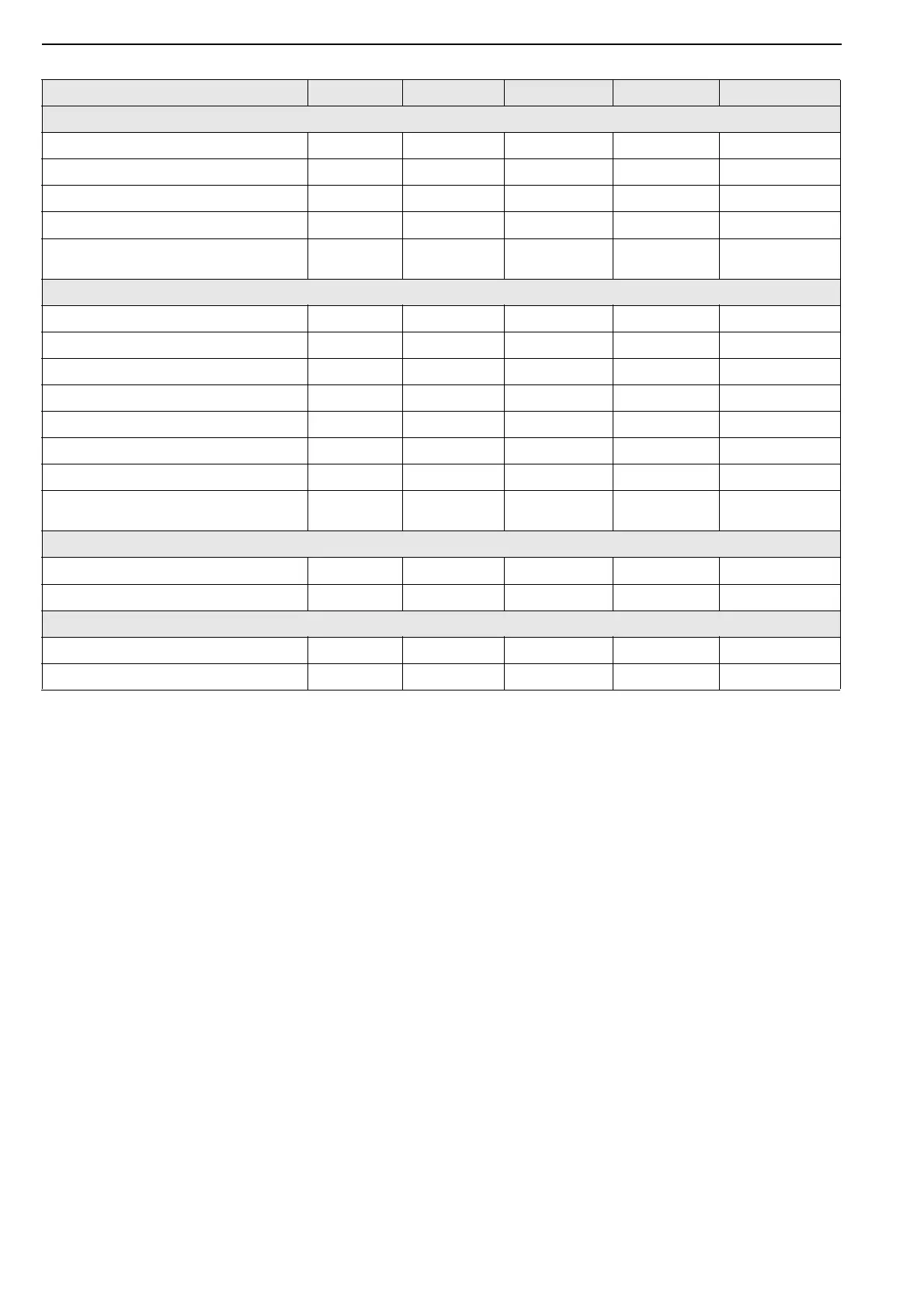
5.3 General Technical Data Table
Electrical load at 230 V 50 Hz measured by calculating from total run current of appliance.
* Do not exceed the maximum length of flue stated or heater may not operate properly. Reduce the
maximum length stated by 1 m for each 90° bend installed.
**If minimum air flow requirements are not met, then temperature limit devices will shut down the heater.
Model CTU-75 CTU-90 CTU-100 CTU-115
CTUA With Axial Fan
Total Electrical Load W 510 510 745 745
Run Current A 1. 9 1. 9 3.2 3.2
Start Current A 2.8 2.8 4.5 4.5
Air Flow m
3
/h 7500 7500 11,000 11,000
Sound P
ressure Level at 3 m [NR] dB(A)
[52.3]
57.3
[52.3]
57.3
[52.3]
57.3
[52.3]
57.3
CTUB with Centrifugal Fan and CTUC Range with Centrifugal Fan and Duct Inlet
Total Electrical Load W 1100 110 0 1650 1650
Normal Run Current A 11.0 11.0 15.6 15.6
Normal Start Curr
ent A 13.5 13.5 19.2 19.2
Normal Speed Medium Medium Medium Medium
High Run Current A 14.0 14.0 21.0 21.0
High Start Curr
ent A 17.2 17.2 25.8 25.8
Air Flow m
3
/h 6400 6400 9400 9400
Sound P
ressure Level at 3 m [NR] dB(A)
[62]
61.8
[62]
61.8
[63]
64.2
[63]
64.2
CTUD Duct Heater with No Fan
**Minimun Air Flow Required m
3
/h 6400 6400 9400 9400
Pressur
e Loss Across Heat Exchanger Pa 30 30 30 30
Flue and AIr Intake
Flue and A
ir Intake Size mm Ø 130 130 130 130
*Maximum Straight Flue/Air Intak
e m 15 17 20 20