Home
COMBAT
Heater
CTU-90
Page 29 (CTUD Wiring Diagram (Models 75-115))
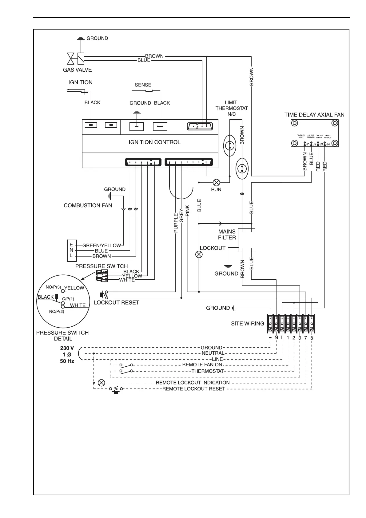
COMBAT CTU-90 - CTUD Wiring Diagram (Models 75-115)
54 pages
Manual
Save Page as PDF
To Next Page
To Next Page
To Previous Page
To Previous Page
Loading...
SECTION 1
1: W
IR
ING
AN
D
E
L
E
CT
RICA
L
I
NFORM
ATION
23 o
f 46
1
1
.
5
CT
UD W
ir
i
n
g
Dia
g
ram
(Mo
de
l
s 75-
1
1
5
)
NO
T
E:
For ext
e
r
nal
f
a
n
w
irin
g,
S
ee P
age 2
4, S
ecti
on
1
1
.6
.
If any o
f the o
ri
g
i
nal
w
ir
e s
u
ppli
ed
w
ith t
he
hea
t
er
m
u
st
b
e rep
laced,
i
t m
u
st b
e re
pl
aced
w
ith
w
iring m
ate
r
ia
l
ha
v
i
n
g a temp
erat
u
re
rating
of at
l
e
ast 1
05
°
C
a
nd 60
0
v
ol
t
s
.
28
30
Table of Contents
Main Page
Default Chapter
3
Table of Contents
3
Table of Figures
8
Table of Contents
8
SECTION 1: Heater Safety
8
Manpower Requirements
8
Safety Labels and Their Placement
8
Figure 1: Side and Back Panel Label Placement
8
Figure 2: Side Panel Label Placement
9
SECTION 2: Installer Responsibility
10
Laminated Wall Plate
10
Corrosive Chemicals
10
National Standards and Applicable Regulations
10
SECTION 3: Clearances to Combustibles
11
Required Clearances to Combustibles
11
Figure 3: Installation Clearances and Clearances to Combustibles
12
SECTION 4: Critical Considerations
13
Ventilation
13
Gas Supply
13
Electrical Supply
13
Flue
13
SECTION 5: Specifications
14
Ctua
14
CTUB, CTUC and CTUD
15
General Technical Data Table
16
Technical Data Table
17
SECTION 6: Heater Installation
18
General
18
Basic Information
18
Location and Suspension
18
Handling
18
Suspension and Shelf Mounting
18
Figure 4: Suspension Methods
19
SECTION 7: Flue Installation
20
Flue Installation
20
Type B Appliance
20
C 32 & C 62 Appliance
20
Figure 5: Flue and Roof Detail
20
Figure 6: Vertical and Horizontal Flue Termination
21
Figure 7: Vertical and Horizontal Flue Termination
21
SECTION 8: Air Supply
22
Room Sealed Installation
22
Open Flued Installation
22
Building Ventilation
22
Isolated Equipment Rooms
22
Figure 8: Heaters Installed in Isolated Equipment Rooms
22
SECTION 9: Optional Heater Configurations
23
Distribution Duct Work for CTUB, CTUC and CTUD Heaters
23
Figure 9: Ducting
23
SECTION 10: Gas Pipe Work
24
Connections
24
Figure 10: Gas Connection with Stainless Steel Flex Connector
25
SECTION 11: Wiring and Electrical Information
26
Electrical Supply
26
Remote Controls
26
CTUA Wiring Diagram (Models 75-115)
27
CTUB/C Wiring Diagram (Models 75-115)
28
CTUD Wiring Diagram (Models 75-115)
29
CTUD External Motor Alternative Wiring & Optional Thermostat/Time Switch
30
SECTION 12: Commissioning
31
Pre-Commission Checks
31
Gas Supply
31
Mechanical Checks
31
Begin Commissioning
32
Figure 11: Sequence of Operation Chart
32
Combustion Testing
33
Turning off the Heater
33
Figure 12: Gas Valve for Heater (Models 75 - 115)
33
External Controls
34
Complete the Commissioning
34
Instruction to the User
34
SECTION 13: User Instructions
35
User Instructions
35
Heater Operation
35
Figure 13: Heater Operating Sequence
35
Common User Controls
36
Lighting Instructions
36
Simple Fault Finding
36
SECTION 14: Servicing
37
Servicing Instructions
37
Burner Maintenance
37
Fan/Motor Assembly Maintenance
37
Heat Exchanger Maintenance
38
Gas Control Valve Maintenance
38
Flue Fan
38
Maintenance Checklist
38
SECTION 15: Conversion between Gases
40
General
40
Burner Conversion
40
Gas Valves
40
SECTION 16: Troubleshooting
41
General
42
Troubleshooting for Automatic Ignition Burner Systems
43
Troubleshooting for Flame Supervision System
44
Troubleshooting for Solenoid Valves
44
SECTION 17: Removal and Replacement Parts
45
Gas Valve
45
Burner Compartment
46
Ignition Electrode and Flame Probe
48
Flue Fan
49
Pressure Switch
50
Ignition Control
51
CTUA Axial Fan/Guard/Motor Assembly
51
CTUB & CTUC Centrifugal Fan/Guard/Motor Assembly
51
Fan Data
52
Figure 14: Centrifugal Fan Orientation
52
Related product manuals
COMBAT CUHA
84 pages
COMBAT Elite ELG 75-235
52 pages
COMBAT 15g
64 pages