SECTION 17: REMOVAL AND REPLACEMENT PARTS
45 of 46
17.6 Ignition Control
IT IS IMPORTANT THAT ONLY THE CORRECT
IGNIT
ION CONTROL SPECIFIED FOR EACH
MODEL TYPE IS USED WHEN REPLACING
THESE ITEMS.
17.6.1 Models 22 to 115
This control is mount
ed at
the electrical mounting
plate. Pull out the 3 cable connectors.
Pull
out
ignition cable, ignition earth and flame probe
cable noting their positions. Remove the screws.
Refit in reverse. Ensure correct location of ignition
and flame probe cables.
17.7 CTUA Axial Fan/Guard/Motor Assembly
The axial fan uni
t
for the CTUA heater is
supplied completely assembled and balanced.
17.7.1 Fan Removal and Replacement
17.7.2 To Replace the Fan Assembly
To replace the fan assembly, revers
e
the procedure
shown above. Fit rubber washers to the guard
mountings to reduce vibration.
• Ch
eck that the fan blades are free to rotate
before turning on the power to the fan.
• Strictly comply with the colour code of the fan
wires to ensure correct operation. See Page 21,
Section 11.3 wiring diagram.
• Use only genuine replacement parts sold and
supplied by Combat.
17.8 CTUB & CTUC Centrifugal Fan/Guard/Motor
Assembly
The direct drive
fan/s for the CTUB & CTUC range is
supplied as a complete assembly. Take careful note
of the electrical connections of the fan before
disconnecting from the terminals.
For the CTUC vers
i
ons fitted with an inlet spigot
assembly, the fans may be accessed through the
removable covers on the sides, top and bottom of
the spigot, as required.
17.8.1 Fan Removal and Replacement
Re
move the fan by remov
ing the fixing screws while
supporting the weight of the fan (approx. 19 kg).
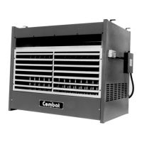
17.8.2 To Replace the Fan(s)
T
o reassemble, revers
e the procedure shown above.
•Fi
t new rubber seal between the fan flange and
the heater rear panel.
•Fit to the rear panel in the correct orientation as
shown on Page 46, Figure 14.
•Strictly comply with the colour code of the fan
wires to ensure correct operation. See Page 22,
Section 11.4 wiring diagram.
•Use only genuine replacement parts sold and
supplied by Combat.
The three speed winding connections are:
Low speed: Wh
ite N, Red Live The other two
windings are "parked" separately in spare terminals.
Medium speed: W
h
ite N, Blue live. The other two
windings are "parked" separately in spare terminals.
High
speed: W
hite N, Black live. The other two
windings are "parked" separately in spare terminals.
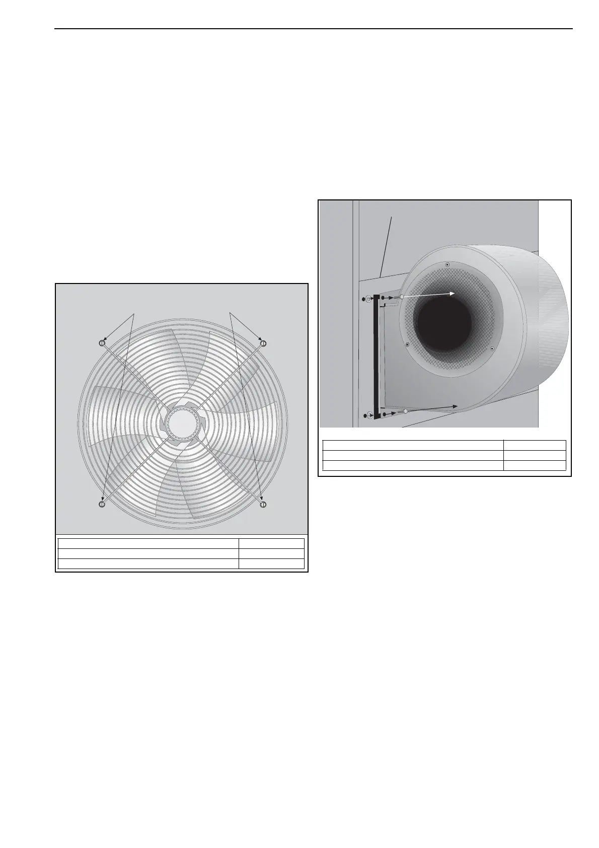
Remove the four screws
and rubber washers.
Description Part Number
Axial Fan 16 in. (Models 75, 90) 90710418
Axial Fan EBM (Models 100, 115) 90710422
20 mm x 5 mm Adhesive Seal
is applied to the flange.
Description Part Number
Torin Fan DDC 270-270 A047
Torin Fan DDC 241-241 A049