SECTION 17: REMOVAL AND REPLACEMENT PARTS
41 of 46
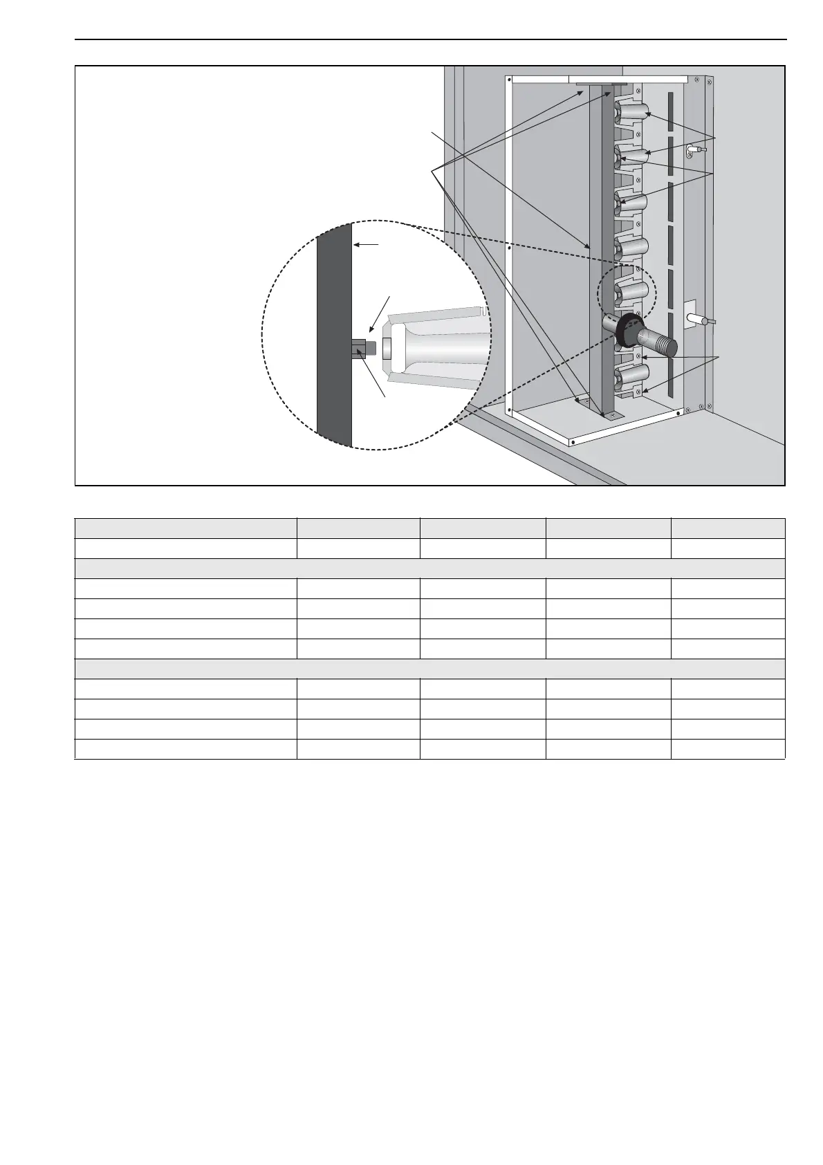
17.2.1 Burner Injectors
Remove manifold
screws and pull
out manifold
Manifold
Burners
Injectors
Burner
Screws
Burner
venturi
Ensure gas tight fitting of injectors.
Ensure correct alignment with burners.
Ensure all pipe joints are gas tight.
MODEL CTU-75 CTU-90 CTU-100 CTU-115
Injector Quantity 12 14 15 17
Natural Gas (G20) and (G25)
Injector size mm Ø 2.71 2.71 2.71 2.71
in Ø 0.1067 0.1067 0.1067 0.1067
Marking 36 36 36 36
RG P/N 91930036 91930036 91930036
91930036
LPG Gas Propane (G31) and LPG Gas Butane (G30)
Injector size mm Ø 1. 5 1 1. 5 1 1. 5 1 1. 5 1
in Ø 0.0594 0.0594 0.0594 0.0594
Marking 53 53 53 53
RG P/N 91930053 91930053 91930053 91930053