ComNav G2 & G2B Installation & Operation
Document PN 29010093 V1.5 - 49 -
16 December 2016
Proprietary Output
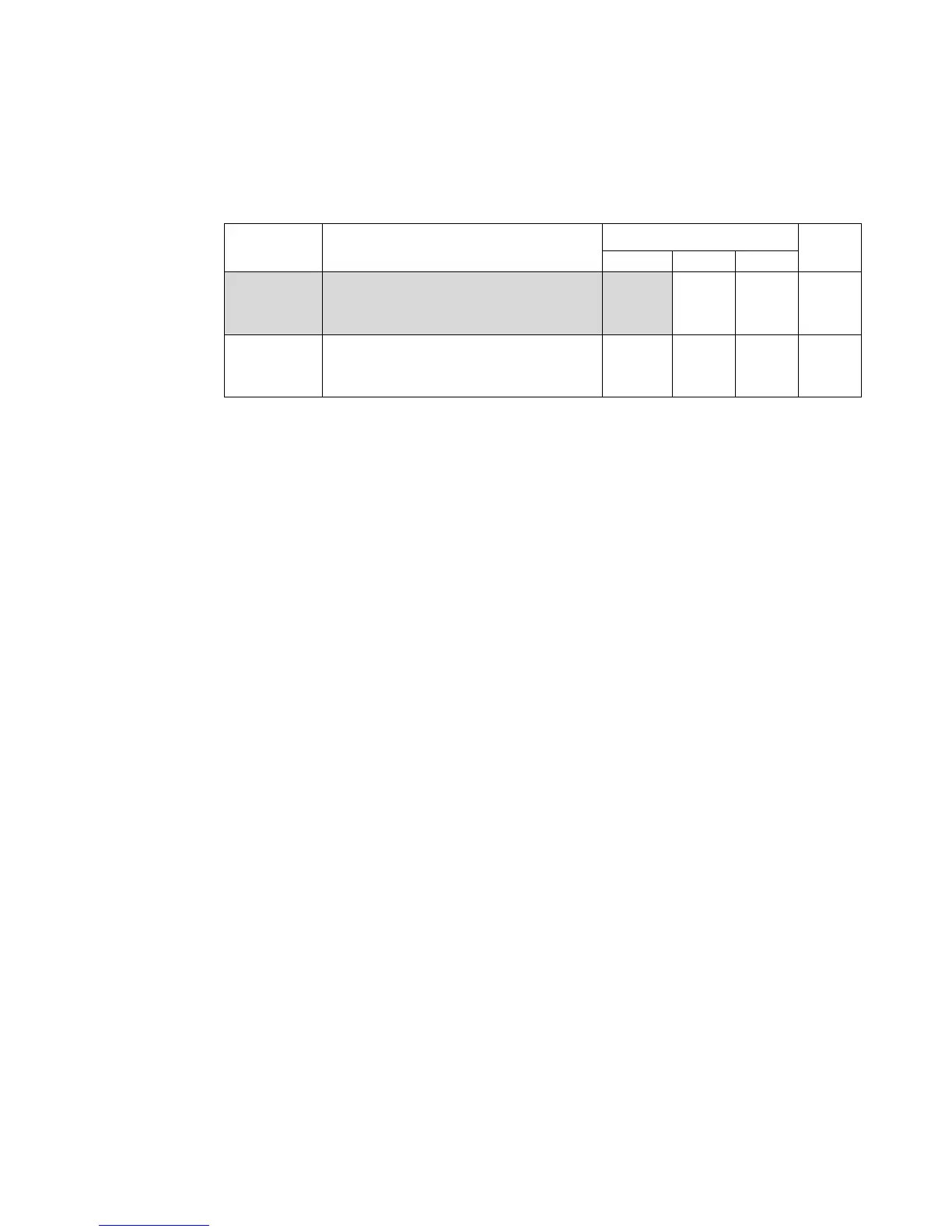
A number of proprietary output sentences are available on the G2/G2B.
Maximum output rates are shown in the far right column, for convenience.
Sentence Description
Enabled
Max
Rate
Port 1 Port 2 Port 3
PCMN,HPR
Time, True Heading, and RTK-based
Pitch (or Roll)
1
X X 10
TSS1 Heave, pitch, and roll X X X 20
Table 7 – Default Proprietary Output Sentences Configuration
Note: none of the proprietary sentences are approved by the IEC for
marine use.
For full details on the G2’s ComNav proprietary sentences, please refer to Appendix 2.
Baud Rate
Each of the G2’s output ports can be configured, independent of each other, to communicate
at all conventional Baud rates from 4800 up to 38400 Baud.
• For software versions below 1.6.0, the factory-default configuration of Ports 1, 2 and
3 is 4800 Baud
• For software versions from 1.6.0, the factory-default configuration of Ports 1 is 38400
and for Port 2 and 3 4800 Baud.
Note: for operation with all ComNav autopilots, the G2’s baud rate must be
4800. For operation with other equipment, other Baud rates may be
allowable, depending on the equipment.
Electrical Interface
Another factor in using the G2 is what type of the electrical interface (i.e., signal levels,
rise/fall times, circuit impedances) the other equipment uses for its Input/Output “navigation
data” connections.
All marine equipment which is fully compliant with the NMEA 0183 Standard (e.g., ComNav
autopilots) uses RS-422 levels only.
Other on-board “NMEA compatible” equipment – e.g., PCs – often uses RS-232 levels.
Alarm Output
G2G2B provides 2 types of alarm output for 3 conditions: Audible alarm output (audible
device drive output) and NMEA 0183 alert management sentences
Audible Alarm output
An Alarm relay is located on the G2’s circuit board. The relay’s contacts are isolated from all
circuitry in the G2 – the G2’s internal processor controls the coil side of the relay, but the
contacts of the relay are connected only to the two Alarm pins on the G2’s I/O connector.
If the G2 is unpowered, or if it is powered but is not able to compute valid heading data (for
example, when it does not have good satellite signals at one of the two antennae. See the
alert condition definition in the next section), the relay coil is de-powered. This causes the