3.4. General 1
The 4th menu item shows the parameterization of general settings 1.
Mains: This selection defines whether the overvoltage and undervolt-
age stages are applicable for the 4-wire (star) or 3-wire (delta)
voltages.
t-Block: The blocking time comes into effect after a mains fault or after
a failure of the auxiliary voltage. The generator system may be
switched on again only if the mains is within the permissible
limits for switching on for a certain period of time (blocking
time). The setting range of the blocking time is 0 s to 900 s.
Aux cont: Here, you can configure the setting for the auxiliary contacts
of circuit breakers. Configurable parameters are N.O. (Normaly
Open contacts), N.C. (Normaly Closed contacts) and OFF. If NC
or NO contacts have been selected, it is checked, after actuat-
ing the relays, whether the auxiliary contacts are switched ac-
cordingly. If auxiliary contacts do not switch within a defined
time range, the relay tries to switch itself on 3 times (after a
pause of 10 s in each case). A fault is notified if the relay fails
to switch on all three times.
To reset an auxiliary contact fault, either restart CDMRE-100 or
enter the number "69" in the "General 3" menu in the "EvtLog
Cl" line (Reset).
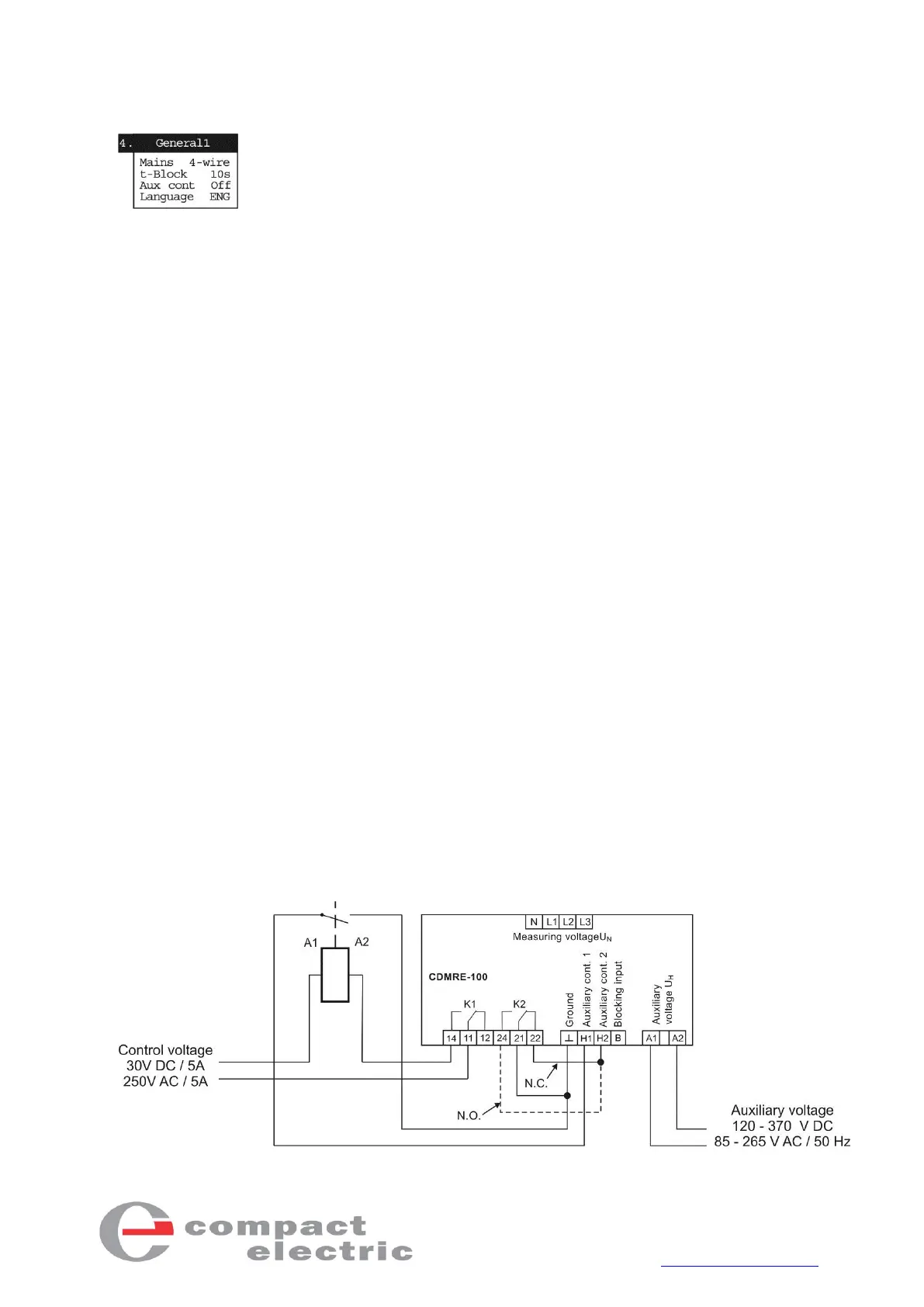
If only one of the two relays is used and connected to a circuit
breaker, and the auxiliary contacts are set to N.O. or N.C., the
unused auxiliary contact input must be connected to the cor-
responding unused relay. In the N.C. setting, ground and auxil-
iary contact 2 must be connected to relay outputs 21 and 22
and in the N.O. setting, ground and auxiliary contact 2 must be
connected to relay outputs 21 and 24 (see figure 7).
Language: You can select GER (German) or ENG (English).