EasyManuals Logo

Compaq Armada E500 Series Maintenance And Service Guide

Compaq Armada E500 Series
162 pages
To Next Page IconTo Next Page
To Previous Page IconTo Previous Page
Page #35 background imageLoading...
Page #35 background image
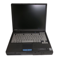
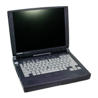
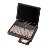
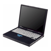
1-28 Product Description
COMPAQ CONFIDENTIAL - NEED TO KNOW REQUIRED
Writer: The Integrity Group Saved by: The Integrity Group Saved date: 10/26/00 12:32 PM
Part Number: 128679-006 File name: Ch01
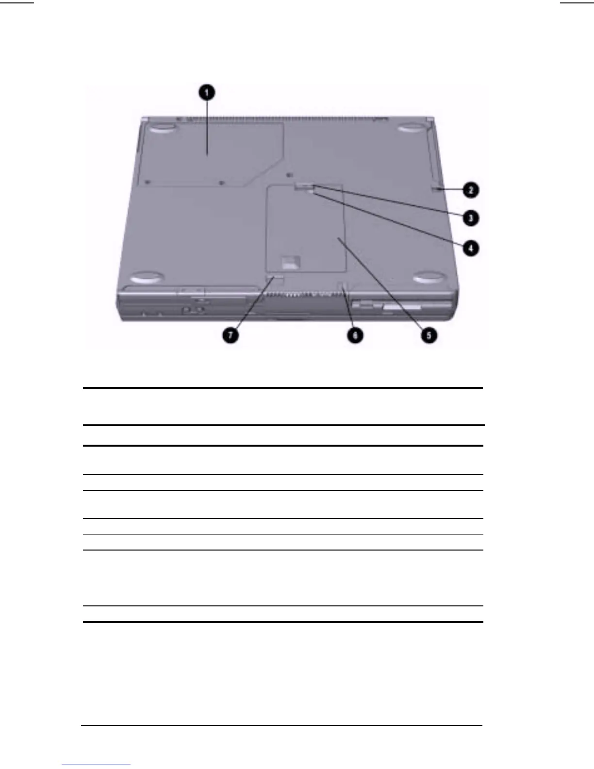
The external components on the bottom of the computer are shown in
Figure 1-7 and are described in Table 1-10.
Figure 1-7. Bottom Components
Table 1-10
Bottom Components
Item Component Function
1 Mini PCI slot cover Contains the mini PCI modem or network
interface card.
2 Battery release latch Releases the battery from the battery bay.
3 Hard drive cover
release latch
Releases the hard drive cover.
4 Hard drive cover screw Secures the hard drive cover.
5 Hard drive cover Covers the hard drive bay.
6 Diskette drive release
latch
Releases the device from the DualBay on
the Armada E500.
Releases the diskette drive bezel from the
Armada V300.
7 MultiBay release latch Releases the MultiBay device.

Table of Contents

Other manuals for Compaq Armada E500 Series

Questions and Answers:

Question and Answer IconNeed help?

Do you have a question about the Compaq Armada E500 Series and is the answer not in the manual?

Compaq Armada E500 Series Specifications

General IconGeneral
ProcessorIntel Pentium III
ChipsetIntel 440BX
Optical Drive24x CD-ROM or DVD-ROM
Networking10/100 Ethernet
WirelessOptional 802.11b
RAMUp to 512 MB
Display14.1-inch TFT, 1024x768 resolution
GraphicsATI Rage Mobility with 8 MB
PortsUSB, Parallel, Serial, VGA, PS/2, Infrared
BatteryLithium-Ion
Operating SystemWindows 98, Windows 2000
Storage6 GB - 12 GB Hard Disk Drive
Battery LifeApproximately 2-3 hours

Related product manuals