Use medium threadlock on all
screws threaded into metal
parts.
Verwenden Sie auf allen
Schrauben die in Metallteile
geschraubt werden mittelfeste
Schraubensicherung.
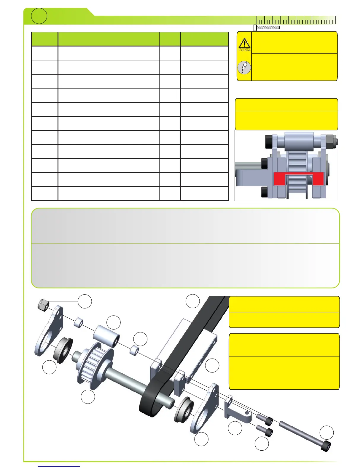
Press bearings (7) into tail sideplates (6). Slide parts from STEP9 (2) into bearings and mount tail
sideplates and tail lever mount (8) with bolts (10) to tail case (5). Now put the tail belt (3) around the
tail belt pulley. Slide spacers (4) and parts from STEP10 (1) between sideplates and secure it with
bolt (9) and nylon lock nut (11).
Pressen Sie die Lager (7) in die Seitenplatten (6). Führen Sie die Teile aus STEP9 (2) durch die
Lager und montieren Sie die Seitenplatten und die Halterung für den Umlenkhebel (8) mit den
Schrauben (10) an das Heckgehäuse (5). Führen Sie nun den Heckriemen (3) um das
Heckriemenrad. Schieben Sie die Abstandshalter (4) und die Teile aus STEP10 (1) zwischen die
Seitenplatten und ziehen sie mit der Schraube (9) und Mutter (11) an.
2
3
4
5
6
1
8
9
10
11
7
Bearings mounted at factory.
Kugellager bereits vormontiert.
Note mounting direction (5)
Achten Sie auf die Einbaurichtung
(5)
Bolts for tailfin are mounted
later.
Die Schrauben für die
Heckfinne werden später
montiert.