Use medium threadlock on all
screws threaded into metal
parts.
Verwenden Sie auf allen
Schrauben die in Metallteile
geschraubt werden mittelfeste
Schraubensicherung.
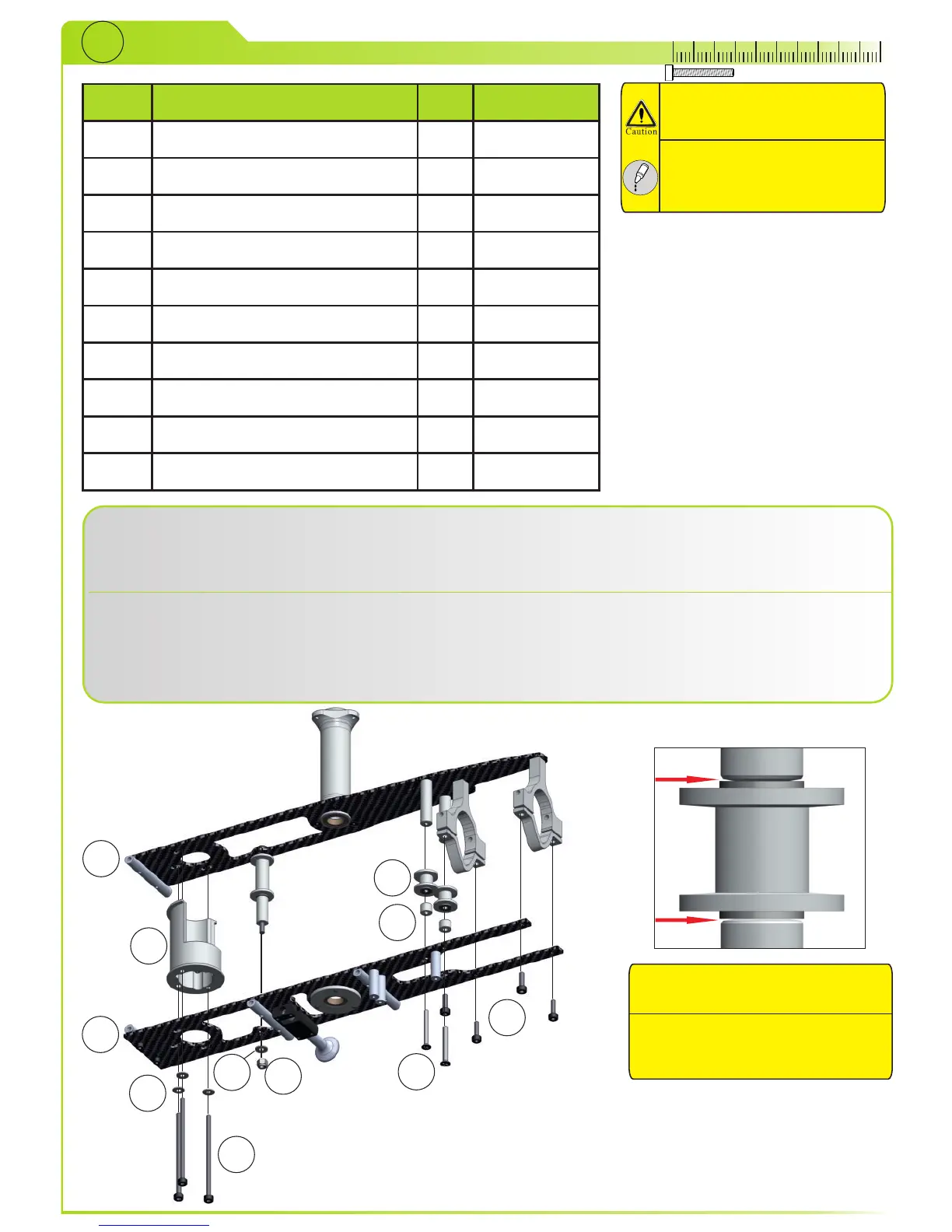
Put motor mount (3), guide wheels (4) and spacers (5) between cf plates from STEP25 and STEP27 (1,2)
and tighten bolts (7, 9) and nylon lock nut (10). Slide bolts (8) through motor mount. Do not forget to put
washers (6) where needed.
Before tightening, pull front guide wheel as far as you can to the outside of the cf plate.
Geben Sie die Motorhalterung (3), die Riemenräder (4) und Abstandshalter (5) zwischen die CFK Platten aus
STEP25 und STEP27 (1,2) und ziehen Sie alles mit den Schrauben (7,9) und der Stopmutter (10) fest.
Stecken Sie die Schrauben (8) durch die Motorhalterung. Vergessen Sie nicht, Unterlegscheiben zu
verwenden.
Ziehen Sie das vordere Riemenrad ganz nach außen, bevor Sie die Stopmutter festziehen.
1
2
3
4
5
6
7
8
9
10
Angled side of spacers should
always face to bearing!
Die Abgeschrägte Seite der Spacer
sollte immer in Richtung Lager
montiert sein.
6